
I remember the day clearly.
I had just approved a new part design. We were on a tight schedule, and I didn’t want to hold things up.
But I didn’t really understand how die casting worked.
A few weeks later, I got the call.
The mold had a problem, a flaw in the design. We had to redo it. That mistake cost us thousands. Not just in money, but in time. And trust.
It hit hard.
If you’re designing parts, managing orders, or leading production, you can’t afford that kind of mistake. I learned the hard way, by doing things backwards.
That’s why I made this guide. So you don’t have to guess. So you can walk into your next project knowing what happens at every step of the die casting process.
You’ll learn how it works from start to finish. You’ll see where things can go wrong. And you’ll know what questions to ask, before it’s too late.
This isn’t theory. It’s real stuff I wish someone had told me.
So let’s dive in!
Step#1 Product Design & Engineering
I’ll be honest, this is the step we used to overlook.
Back when we launched our first aluminum housing project, we handed over a clean-looking 3D file to the supplier and thought we were ready for tooling. But after two weeks of silence, their engineering team came back with 5 red flags and a hefty redesign quote.
That’s when it hit me: if your part isn’t designed for die casting, you’re not ready to move forward.
Importance
If your design can’t be cast cleanly, it doesn’t matter how sharp it looks on screen.
Die casting has specific rules, and skipping them means extra cost, slower lead times, and rejected parts. Whether you’re working with aluminum, zinc, or magnesium, your design must support the process, not fight against it.
Principles
Let’s cover the non-negotiables:
- Uniform Wall Thickness: Thin here, thick there? That’s a recipe for warping, shrinkage, and flow issues. Stick to a consistent wall thickness whenever you can. You’ll get stronger parts and better fill.
- Proper Draft Angles: Add taper. Always. Even 1–3° of draft helps the part eject cleanly from the die. No draft = sticking = damaged parts = damaged mold. Simple fix. Huge impact.
- Avoiding Undercuts: Undercuts = side actions = more complex tooling = higher cost. Ask yourself: Can we redesign this feature to avoid it? If not, at least plan for the tooling impact.
Simulation
Don’t leave it to chance.
Use CAD software that lets you simulate fill flow, thermal stress, and mold behavior. It’s much cheaper to find a weak point in a simulation than to find it on your production floor, after you’ve already cut steel.
Collaboration
The best outcomes I’ve seen? They always happen when designers and toolmakers collaborate early.
You may have a beautiful model, but your tooling engineer knows what will and won’t cast properly. A 30-minute design review can prevent a 3-week delay down the road.
Bring your manufacturer in early. Share your goals. Get feedback before finalizing geometry. You’re not just designing a part, you’re designing for a process.
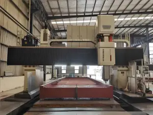
Step#2 Mold (Die) Design & Fabrication
This is where your ideas start turning into reality, but only if your tooling is done right.
I remember the first mold we ever commissioned. It looked perfect on paper. Clean design. Premium steel. But within two weeks of running the first batch, the core started wearing down.
The cooling wasn’t balanced, and parts came out warped. We learned fast: in die casting, mold is the process.
Importance
The mold (or die) is the heart of your die casting operation.
It shapes the part, defines its surface finish, and determines how long your production will stay on track. A well-designed mold keeps your output consistent and your scrap rate low.
A bad one? It bleeds time, money, and trust.
Structure
A standard die is made up of two halves, the cavity (fixed half) and the core (moving half). But that’s just the surface.
Here’s what’s happening inside:
- Ejector pins to push the part out
- Cooling channels to control temperature
- Air vents to prevent trapped gas and porosity
- Slides and cores for complex geometry
If even one of these elements is poorly designed, your entire process suffers.
Steel Matters
The steel you choose for your mold isn’t just about durability, it’s about performance.
Tool steel is the go-to for die casting molds. But not all tool steel is created equal. It must withstand repeated cycles of high pressure and extreme heat without cracking or deforming. Thermal fatigue, erosion, and soldering can destroy a mold fast if the material choice is wrong.
Cooling
Poor cooling ruins more castings than most people realize.
If one section cools faster than another, the part warps. If heat builds up inside the mold, your cycle times slow down. You end up with internal stress, inconsistent dimensions, or worse—scrap.
A good mold has balanced cooling designed around your part’s geometry, not just the mold layout.
Design for Production
Too often, businesses focus only on the part design and forget the tooling design. That’s a miss.
The mold should be designed for efficient, repeatable production:
- Smooth material flow
- Fast ejection
- Minimal wear
- Ease of maintenance
This is why you need a fabrication partner that understands both sides: design and production.
At MachMaster, we don’t just fabricate molds, we help you design them to perform.

Step#3 Melting the Metal
This is the part that looks simple, heat the metal and pour it in, right?
That’s what I thought too, until we got back a batch of castings with brittle corners and surface defects.
The issue? The metal had been overheated, and small gas pockets formed during solidification. One error at this stage, and your whole casting suffers.
Importance
Melting isn’t just about reaching a certain temperature.
It’s about controlling purity, consistency, and flow, because the strength, appearance, and stability of your part all depend on it. Get it wrong, and you’re looking at defects like porosity, blistering, or cracks.
Furnaces
There are two main furnace types used in die casting:
- Induction Furnaces: Clean, fast, and highly controlled. Perfect for aluminum and magnesium alloys. Uses electromagnetic currents to heat metal with precision.
- Gas-Fired Furnaces: More cost-effective and common for high-volume zinc or aluminum. Slightly harder to control, with a higher risk of oxidation or contamination.
Each type has pros and cons, what matters is that the system matches your alloy and quality standards.
Temperature Control
Every alloy has its sweet spot.
Too cold? You won’t get a full fill.
Too hot? You risk shrinkage, mold damage, or brittle castings.
Look for:
- Real-time temperature monitoring
- Automated holding and pouring systems
- Tight control around the alloy’s optimal melt range
This kind of control helps ensure your metal performs the same way every single cycle.
Alloys
Here are the 3 most common die casting metals:
| Alloy | Strengths | Common Uses | Melting Point | Notes |
| Aluminum | Lightweight, corrosion-resistant, good strength-to-weight ratio | Automotive parts, housings, tools | ~660°C (1220°F) | Most widely used. Requires de-gassing. Sensitive to contamination. |
| Zinc | Excellent dimensional accuracy, smooth finish, long mold life | Consumer products, connectors, small enclosures | ~420°C (788°F) | Lower melting temp = faster cycles & cheaper molds. Heavy vs. aluminum. |
| Magnesium | Ultra-lightweight, good mechanical strength, shock absorption | Aerospace, electronics, power tools | ~650°C (1202°F) | Flammable in molten state. Needs special handling. Higher material cost. |
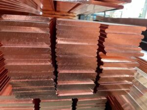
| Copper Alloys | High strength, excellent conductivity, corrosion resistance | Electrical hardware, marine parts | ~1000°C (1832°F) | Expensive and harder to cast. Less common in high-volume die casting. |
Each metal behaves differently in molten form. Your design and tooling must match the alloy you choose. If weight reduction or thermal conductivity is a key concern for your product, this table can help guide your alloy selection before tooling begins.
Still unsure? At MachMaster, we help you match the right alloy to your production goals.
Purity
Contaminated metal = weak parts.
Even if it looks fine on the outside, poor melt hygiene leads to:
- Surface defects
- Internal voids
- Reduced mechanical performance
That’s why your process must include:
- Clean melting tools
- Proper skimming of dross
- Quality-certified metal ingots
Especially in high-risk industries, metal cleanliness is non-negotiable.
Step#4 Injection into Mold
This is where everything happens, fast.
I still remember the first time I saw a real die casting machine fire. It sounded like a punch. Molten metal shot into the mold and, before I could blink, it was done. Milliseconds.
That’s all it takes. But behind that speed? A ton of control.
Importance
This step determines how well the cavity is filled, how strong the final part will be, and whether or not you’ll be chasing down defects later.
Inconsistent fill? You get air pockets.
Wrong pressure? The metal won’t flow cleanly.
Poor timing? The mold cools too fast.
Everything in this phase is about precision at speed.
High-Pressure Injection
Die casting isn’t slow-pour like sand casting.
We’re talking extreme pressure, typically 700 to 1000 bar (and sometimes more). That force is what drives molten metal into every corner of the mold, even thin-walled or intricate features.
The shot sleeve fills, the piston fires, and the cavity is filled in milliseconds faster than the blink of an eye.
This speed is why die casting can produce complex shapes with fine detail and excellent surface finish.
Purpose
2 big reasons this step matters:
- Ensure Complete Cavity Fill: If the mold doesn’t fill all the way, you’ll get short shots or misruns. That’s wasted material and wasted time.
- Prevent Porosity or Shrinkage: If metal flow is too slow or uneven, gases get trapped. That creates voids or weak spots inside the part, especially around thick sections.
The faster and more evenly you fill the mold, the better the outcome.
Parameters to Monitor
Smart teams and good suppliers don’t “wing it” here. They dial in very specific settings for every shot:
- Injection Speed: Needs to match part complexity and mold layout. Too fast = turbulence and air entrapment. Too slow = incomplete fill.
- Pressure: Must stay consistent to push metal into every detail. Drops in pressure cause flow hesitation and weak bonding.
- Temperature: Both the metal and the mold need to be at optimal temperature. If either is off, flow is compromised and part quality suffers.
These variables are usually monitored and logged digitally, especially in high-volume production. If your supplier can’t provide those logs when you ask? That’s a problem.

Step#5 Cooling and Solidification
Once the metal fills the mold, everything goes quiet, but this phase is just as critical as the injection.
I remember waiting beside a cold chamber machine during a trial run. The part had filled perfectly, but came out warped.
Why? Uneven cooling. One side solidified too fast, while the other side held heat. It looked fine at first glance, but it failed fit testing later.
That’s when I learned: cooling isn’t passive, it’s engineered.
Importance
Just because the mold is full doesn’t mean the part is ready.
This stage is all about locking in shape, strength, and dimensional accuracy. The mold stays closed, holding the part in place while it transitions from liquid to solid.
If cooling happens unevenly or too quickly, you end up with:
- Warping
- Cracking
- Internal stress
- Poor surface finish
Done right, cooling sets the part up for success in ejection and beyond.
Cooling Time
Cooling isn’t one-size-fits-all. It depends on three key factors:
- Part Geometry: Thicker areas hold heat longer. Thin-walled sections cool faster. Irregular shapes require more precise thermal control.
- Material: Different alloys solidify at different rates.
- Zinc cools fast
- Aluminum takes longer
- Magnesium needs careful balancing
- Mold Temperature: A mold that’s too hot leads to longer cycles and soft castings. Too cold, and you get premature solidification before full cavity fills.
The goal is to balance all 3 factors, so the part cools evenly and efficiently.
Cooling Channels
This is where real mold engineering shines.
Cooling channels, built directly into the mold, allow coolant (usually water or oil) to flow through key areas. They pull heat away from the part, speeding up solidification while preventing hotspots.
The best molds are designed with:
- Uniform cooling distribution
- Flow paths that target thick or isolated areas
- Sensors to monitor thermal performance in real time
Without this? You’re guessing. And in die casting, guessing is expensive.
Step#6 Ejection of the Casting
This is the moment everyone watches, when the mold opens, and the part finally emerges.
But I’ll tell you this: I’ve seen great castings ruined at this very step. One project we ran years ago had perfect fill, solid cooling, and top-notch metal quality. But the ejection pins were misaligned, and they left deep dents in every part.
That entire batch? Scrapped.
It’s not enough to make the part, you have to release it cleanly.
Importance
Ejection may seem like a simple mechanical action, but it plays a critical role in part quality, tooling life, and cycle efficiency.
Done right? You get a clean, undamaged part.
Done wrong? You’re looking at warping, cracks, or dents, and possibly even mold damage.
Clean ejection reduces scrap, protects your tooling investment, and keeps your production running smoothly.
Ejector Pins
Ejector pins are the most common mechanism for pushing the solidified part out of the die.
- They’re embedded in the movable half of the mold.
- Once the mold opens, the pins extend and gently push the part forward.
- Then they retract, resetting for the next cycle.
Pin placement is key.
If they’re positioned in thin or fragile areas, they can deform the part. If they’re spaced poorly, you get uneven force, which leads to warping or cracking.
A well-engineered mold considers not just the shape of the part, but how it needs to be released.
Parting Lines and Ejection Marks
Every casting will have a parting line, the thin seam where the two halves of the mold meet.
You’ll also see ejection marks where the pins make contact. These should be:
- Small
- Consistent
- Placed in non-critical or hidden surfaces
If you’re seeing large dents or visible defects at these points, it means the ejection system needs adjustment, or the part is sticking due to poor draft angles or lubrication.
Manual vs. Automated Ejection
Depending on your operation and part complexity, ejection can be:
- Manual
- Common in low-volume or prototype runs
- Operator removes part with gloves or tools
- Slower and more prone to variation
- Automated
- Standard in high-volume production
- Uses ejector pins, air jets, or robotic arms
- Consistent, repeatable, and faster cycle times
For most industrial applications, automation is the smarter move, especially when mold life and output speed matter.
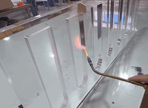
Mold Lubrication and Cycle Time
A small but critical detail: lubrication.
Lubricants help the part release more easily and protect the mold surface from sticking or wear. They also:
- Reduce the risk of tearing or pulling
- Extend mold life
- Improve surface finish
But too much lubrication? It can leave residue, affect part quality, or create a fire hazard if not properly managed.
Balanced, well-applied lubrication keeps ejection clean and keeps cycle time short, which is essential for meeting production targets.

Step#7 Trimming and Removal of Excess Material
You’ve got a solid, fully-formed part in hand—but it’s not quite finished yet.
When I first toured a high-volume casting facility, I noticed stacks of parts that looked rough around the edges literally. Each one had extra bits of metal hanging off the sides.
That’s when the plant manager leaned in and said, “Now we clean them up and make them look like something you’d actually want to use.”
This step is where the raw casting becomes usable.
Importance
Die casting is efficient, but it’s not perfectly clean by default.
During injection, molten metal not only fills the part cavity, it also flows into channels that help control pressure and temperature. Once cooled, you’re left with:
- Sprues
- Runners
- Overflow tabs
- Flash (thin layers of excess metal at parting lines)
All of that needs to go, quickly, cleanly, and without damaging the part.
What Gets Trimmed
Here’s what’s usually removed after ejection:
- Sprues – the main inlet through which metal enters the cavity
- Runners – small channels that direct flow
- Overflows – safety zones that capture excess metal
- Flash – unwanted metal along parting lines or ejector pin sites
Even the best mold can produce some amount of flash. The key is to minimize it through good mold design and to remove it efficiently during trimming.
Trimming Methods
There are several ways to trim and clean parts, some fast, some precise, some both:
- Manual Trimming
- Workers use hand tools, files, or snips
- Common for prototypes or small runs
- Slower and depends heavily on operator skill
- Hydraulic Trim Presses
- The most common method in mid-to-high-volume production
- Parts are placed into a trim die that punches off excess material
- Fast and consistent, but requires proper die setup
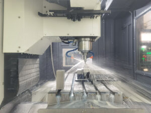
- CNC Machining
- Used when precision is critical
- Ideal for tight tolerances or secondary machining needs
- Adds cost but improves accuracy
- Deburring (Optional)
- Smooths out edges for safety, aesthetics, or assembly
- Can be done by tumbling, brushing, or hand-finishing
Each method depends on your product’s end-use. A decorative part may require more finishing than a hidden bracket or internal housing.

Step#8 Final Inspection
This is where everything either gets approved or stopped in its tracks.
I remember walking through a client’s QC department during a rush order. Parts were flying off the trim press, and the team was moving fast.
But one casting failed a fit check. Then another. Turns out the temperature setting had drifted during a long run. Because they caught it here, they saved the entire batch from going out flawed.
Final inspection isn’t a formality. It’s your last line of defense.
Importance
Die casting is precise, but it’s not immune to variation.
From raw material inconsistencies to tool wear or temperature shifts, there are dozens of things that can go wrong during a production run. That’s why every part, or at least every batch, should be inspected before packaging or assembly.
Inspection ensures that every component meets your functional, dimensional, and visual requirements before it hits your supply chain.
What Gets Checked
At this stage, your quality control team (or your supplier’s) should be looking at:
- Dimensional Accuracy: Measured with calipers, gauges, or Coordinate Measuring Machines (CMM). Focus on critical tolerances for mating surfaces, holes, slots, etc.
- Surface Quality: Look for pitting, cracks, blisters, or flashing left behind. Some industries allow cosmetic flaws—others don’t
- Internal Defects (if applicable): For structural or load-bearing parts, X-ray or ultrasonic testing may be required. This is especially critical in aerospace, medical, or high-safety applications
- Thread and Feature Checks: If post-machining is involved, threads, grooves, or tapped holes must be tested for proper fit and finish
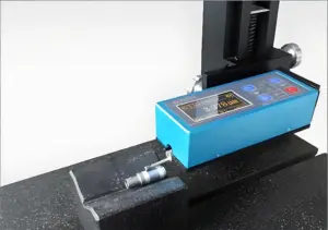
Inspection Tools
Here are some common tools and methods used in a professional die casting inspection:
- Visual inspection stations
- Digital calipers and micrometers
- Go/No-Go gauges
- Surface roughness testers
- X-ray or CT scanners (for internal porosity detection)
- CMMs for high-precision dimensional analysis
The tools used depend on your industry, tolerances, and the end use of the product.

Conclusion
You now understand the die casting process, step by step.
From molten metal to finished part, each stage has a purpose.
Use what you’ve learned to make better decisions. Ask clearer questions. Plan with confidence. Whether you’re talking to your team, your supplier, or your client, you’ll know what matters.
If you’re looking for a partner who knows this process inside and out, Machmaster is a solid place to start.
What’s holding you back from moving forward?
Contact us now. We’re here to help.
Explore More of Our Resources
If you’re searching for more choices, explore our full collection of products. We’ve picked out some great options for you:
- Anodizing Service
- Cnc Milling Service
- Cnc Turning Service
- Injection Molding Service
- Cnc Machining Service
Want to learn more? Here are some articles filled with valuable tips and information to guide you further:
Still haven’t found what you’re looking for? Don’t hesitate to contact us. We’re available around the clock to assist you.