
I used to dread bending metal.
No matter how careful I was, something always went wrong. Wrong angle. Wrong position. Sometimes it cracked.
I felt stuck. Like I was missing something.
Over time, I learned the steps that really matter. And it changed everything.
I’m writing this because I know what it’s like to be unsure. If that’s you—don’t worry. This article will help.
I’ve worked hands-on in fabrication for years. Now I’m here to show you what I’ve learned. We’ll go through the key steps in the sheet metal bending process—clearly and simply.
By the end, you’ll feel more confident and ready to do it right.
Let’s jump in!
Quick Guide
Before we get into the full details, here’s a quick snapshot of each step. This gives you a solid starting point before we dive deeper into the full process.
| Step | What To Do |
| Step #1 Choosing the Right Material | Select a metal that fits your job’s strength, corrosion resistance, and formability needs. Test samples and log bend behavior. |
| Step #2 Design and Blueprint Creation | Build a clear CAD layout with bend allowances and tolerances. Share files in proper formats with the shop. |
| Step #3 Marking the Bend Lines | Clean the sheet, measure from fixed edges, and mark bend lines clearly. Double-check angles and bend directions. |
| Step #4 Clamping the Sheet | Align the sheet over the die and secure it firmly. Confirm flat contact and proper orientation before bending. |
| Step #5 Choosing the Right Bend Setup | Choose punch and die that match your material and bend specs. Adjust press brake settings for consistency. |
| Step #6 The Bending Operation | Run a test bend first. Then bend production parts using consistent speed, force, and technique. Check as you go. |
| Step #7 Springback Compensation | Measure post-bend angles and adjust with overbend or tooling changes. Track results by material type. |
| Step #8 Inspection and Quality Control | Check angles, dimensions, and surface finish. Record results and use templates or gauges for fast verification. |
Now that you’ve seen the big picture, let’s break down each step, one at a time.
Step#1 Material Selection
Every successful bend starts with the material. Before any sketching or brake setup happens, it’s important to understand the type of metal being used. This decision shapes every other step—from planning the bend to final part performance.
In the early days, I often grabbed whatever was on hand, only to see the material fail under pressure. It wasn’t until I began matching metal properties to the job at hand that things improved.
Understand the Application
- Identify Functional Needs: List the part’s purpose—structural, visual, or both—and identify load and exposure factors.
- Document Use Conditions: Specify if the part will operate in heat, humidity, vibration, or contact with chemicals.
- Select Based on Conditions: Match the metal’s properties—tensile strength, corrosion resistance, formability—to the job’s requirements.
Compare Common Material Types
- Choose the Base Metal: Pick aluminum for lightweight needs, mild steel for balance, stainless for durability, or copper/brass for decorative work.
- Review Past Projects: Look at similar jobs to confirm which metals worked best in similar forming setups.
Thickness and Bend Behavior
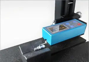
- Measure and Note Sheet Thickness: Confirm and document material thickness using a caliper or sheet gauge.
- Cut and Test Sample: Bend a small sample strip to observe cracking, wrinkling, or springback.
- Log Springback Observations: Record how far the test piece returns after bending and adjust future bend angles accordingly.
Material choice affects everything downstream. It’s worth investing the time to get this part right.

Step#2 Design and Blueprint Creation
After selecting the proper material, the next move is creating a clear, detailed plan. This step ensures each bend, cut, and dimension aligns with expectations. Without it, production teams are left making assumptions—and that usually leads to mistakes.
Develop a Precise CAD Drawing
- Open CAD Software: Use tools like AutoCAD or SolidWorks to begin designing a 2D or 3D model.
- Draw the Flat Pattern: Lay out the part’s flat state with all planned bend lines clearly marked.
- Apply Bend Allowance: Adjust the design by adding bend allowances to maintain correct final dimensions.
- Add Inside Radius Callouts: Specify the inside radius at each bend to align with die selection and material limits.
Define Manufacturing Parameters
- Enter Material Specifications: Clearly indicate the selected metal type and thickness in the title block or notes section.
- Input Tolerances: Add tolerance values for each dimension that needs tight control—especially bends and critical fit areas.
- Insert Post-Processing Notes: Indicate any polishing, deburring, or coating steps required after forming.
Export and Share the Blueprint
- Save in Accepted Formats: Export the drawing as DXF, DWG, or STEP depending on shop requirements.
- Generate a Bend Table: Include a table that lists bend locations, angles, radii, and sequence.
- Distribute With Explanation: Send the files with a brief outline or checklist highlighting critical areas or steps.
Blueprints are more than drawings—they are instructions that connect everyone involved in the project. A thoughtful design process supports accurate, efficient fabrication.
Step#3 Marking the Bend Lines
Once the blueprint is finalized, it’s time to apply the plan to the actual sheet. Marking bend lines correctly helps ensure the material is placed, aligned, and bent exactly where intended. Even a few millimeters off can affect how a part fits or functions.
Prepare the Sheet for Marking
- Clean the Surface: Wipe off any dust, grease, or residue using a lint-free cloth and alcohol or degreaser. At MachMaster, we make sure that every sheet is cleaned thoroughly before layout begins—because a clean surface means accurate marks and better bends.
- Secure the Sheet on a Flat Surface: Use a clean workbench or inspection table to stabilize the material before measuring.
- Measure from a Fixed Reference Edge: Use a steel ruler or caliper to take measurements from a defined corner or edge—this keeps the layout consistent.
- Mark Bend Lines Using Scriber or Marker: Apply fine, straight lines that are easy to read but not so deep that they damage the material surface.
Double-Check Orientation and Sequence
- Verify Direction of Bends: Refer to the drawing to mark which bends go up and which go down.
- Label Bend Angles or Order: Add a quick note next to each line (like “45° up” or “Step 2”) to guide the bending process.
- Compare to Drawing Again: Use the flat pattern printout to double-check that all lines match what’s planned.
- Highlight Critical Lines: Use different colored markers if needed to distinguish key bends or first-step operations.
This step might seem simple, but it’s often where projects succeed or start slipping. A few extra minutes spent on clear, accurate markings can save hours during setup and bending.

Step#4 Clamping the Sheet
With all bend lines marked, the next move is to fix the sheet securely in place before any bending begins. Proper clamping prevents shifting, warping, and inaccurate bend angles. It also allows for repeatable results in multi-part production. A small misalignment here can lead to big errors later.
I learned that first-hand when I clamped a stainless sheet too loosely. It shifted just slightly—but enough to throw off every bend after that. I spent more time correcting those errors than if I had just slowed down to check the alignment properly. Now I never skip the double-check.
Align and Position the Sheet
- Place the Sheet Over the Die: Center the sheet so the bend line aligns exactly with the V-groove of the die.
- Set the Back Gauge: Adjust the back gauge to the correct depth based on the drawing.
- Install Edge Guides or Stops: Lock in guide plates to hold the material steady and consistent across batches.
- Check Face Orientation: Make sure the correct side of the sheet is facing up or down based on the bend direction.
Secure the Sheet Without Damage
- Clamp the Sheet Firmly: Use the brake’s clamping system to apply even pressure along the work area.
- Inspect for Uniform Contact: Confirm that the material sits flat with no lifting, bowing, or twisting.
- Tighten Carefully: Apply enough force to secure without distorting thinner materials.
- Double-Check Alignment Before Bending: Reconfirm the bend line is still in position and has not moved during clamping.
This step is easy to rush—but slowing down here avoids problems later. Some of the cleanest, most consistent bends I’ve made started with a solid clamp setup. It’s a step I never overlook anymore.

Step#5 Bend Setup Selection
With the sheet securely clamped and aligned, the next focus is selecting the appropriate bend setup. This involves choosing the right punch and die combination and adjusting the press brake settings to match the job’s design requirements. A correct setup leads to better consistency, safer operation, and less chance of part rejection.
It took me a while to appreciate how tooling selection changes everything. Once, I used the wrong die opening for a thick aluminum part—and it cracked along the bend. The right setup makes all the difference in forming quality and repeatability.
Select the Proper Tooling
- Identify Bend Radius Requirements: Review the drawing to determine the required inside bend radius.
- Choose the Die Opening: Select a die opening based on material thickness and bend angle. A common rule is 8x material thickness for mild steel.
- Match the Punch Profile: Use a punch with the correct tip radius and shape to suit the bend geometry.
- Verify Tool Compatibility: Ensure the punch and die are rated for the material type and press tonnage.
Configure the Press Brake Settings
- Install Tooling in the Brake: Load the selected punch and die into the press brake and align them.
- Set the Back Gauge Position: Adjust the back gauge to control the bend location per the drawing.
- Input Bending Parameters: Enter the bend angle, material type, and thickness into the machine’s control system if using a CNC brake.
- Run a Dry Test: Cycle the brake slowly without material to confirm alignment and stroke settings.
Taking the time to choose and set up the correct tools is key to getting predictable bends. It’s a step that reinforces both quality and confidence on the shop floor.

Step#6 Bending Operation
Once the setup is complete and all adjustments are locked in, it’s time to begin the bending operation itself. This is where the actual forming takes place—where flat sheet becomes shaped part. A smooth and consistent bend depends on careful handling, proper pressure, and verifying results as the process goes on.
Execute the Initial Bend Safely
- Insert the Test Piece First: Place a scrap sheet of the same material into the brake for a trial run.
- Lower the Ram Slowly: Engage the press brake gently to observe how the tooling interacts with the material.
- Inspect the Bend Angle Immediately: Use a protractor or angle finder to check if the result matches the drawing.
- Adjust Ram Depth as Needed: Modify the stroke or angle setting if the test bend is too shallow or too deep.
Proceed with Production Bends
- Load the First Production Sheet: Position the workpiece in the same spot and alignment as the test piece.
- Perform the Bend Consistently: Use the same speed, pressure, and technique for each part to maintain uniformity.
- Inspect Each Bend During the Run: Spot-check angles and alignment to catch any issues early.
- Log Results for Repeat Jobs: Record pressure, die, punch, and angle settings for use in future runs.
This step is where all preparation pays off. There’s nothing quite like seeing a perfect bend form after getting everything lined up just right. It’s the moment where raw material becomes something usable—and that always feels rewarding.

Step#7 Springback Compensation
After a bend is formed, the material often doesn’t stay exactly at the intended angle. It tries to return slightly to its original shape—a reaction known as springback. This behavior varies depending on the type and thickness of the metal. Without compensation, final angles can drift several degrees from the target.
This step surprised me during early production runs. Angles looked perfect during bending but measured off just minutes later. I didn’t know what caused it until I started tracking behavior by material. That shift in attention helped me improve consistency job after job.
Measure and Adjust for Springback
- Inspect the Test Bend Angle: Use an angle finder or protractor to measure the test piece after releasing it from the press brake.
- Calculate the Springback Difference: Compare this reading to the intended angle and determine how much it opened.
- Apply Overbend Correction: Increase the bend angle slightly when programming the brake to achieve the correct result.
- Repeat a Test Bend to Confirm: Form another sample using the new setting to verify the final angle holds steady.
Optimize Tooling and Technique
- Switch to Bottoming or Coining: Change to a method that forms the bend deeper into the die to help minimize rebound.
- Use a Smaller Punch Radius: Tooling with a tighter radius can reduce the elasticity of the material during forming.
- Record the Material Behavior: Keep a running log for each alloy, thickness, and bend angle to build reference data.
- Verify Every Few Pieces: During large runs, stop at intervals to confirm the angles remain within tolerance.
Springback is one of those challenges that doesn’t go away—but it becomes manageable with habit and experience. Once the patterns are known, it’s easier to anticipate and correct early on. Over time, this step becomes second nature to any fabricator focused on quality..With a bit of patience and the right setup, it’s easy to stay accurate and consistent.

Step#8 Inspection and Quality Control
Even with careful setup and execution, the final check matters most. Inspection ensures that each bent part meets the required dimensions and tolerances. Quality control isn’t about doubting work—it’s about confirming it.
At MachMaster, this is where our dedication to craftsmanship shows. Every part that leaves our floor goes through rigorous inspection—because we know the final step is what protects everything that came before it.
Perform Dimensional and Visual Checks
- Check Bend Angles with Gauges: Use angle finders or digital protractors to verify each bend matches the specification.
- Measure Critical Dimensions: Confirm overall length, flange height, and hole positioning with calipers or tape measures.
- Inspect for Surface Damage: Look closely for cracks, scratches, or deformation around the bend area.
Final Verification and Documentation
- Use a Go/No-Go Template: Test key fit areas with pre-made templates to confirm clearance or fit with mating parts.
- Record Inspection Results: Log measurement data for each part or batch to help with traceability and future repeat orders.
This final step brings everything full circle. A strong inspection routine keeps surprises out of the finished product and adds credibility to the process. It’s a reflection of the pride and care that went into each part.

Conclusion
You made it through every step—nice work. Sheet metal bending used to frustrate me too. Now? With the right process, it feels second nature.
This isn’t about being perfect. It’s about learning what works and applying it.
Feeling ready to start your next project? Let MachMaster handle your precision CNC machining—fast, accurate, and reliable.
Contact us today and let’s build something great!
More Guides and Tips to Explore
We’ve got more for you! These articles provide more tips and guidance to keep you on track:
Still haven’t found what you’re looking for? Don’t hesitate to contact us. We’re available around the clock to assist you.