
The first time I worked on a plastic mold, I thought I was ready.
The design looked great on my screen. Everything lined up. I was sure it would work.
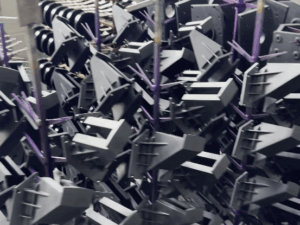
But when the actual part came out of the mold, it was warped. It didn’t fit. It was useless.
We lost weeks fixing it. And it wasn’t cheap.
That was a tough lesson. But it taught me something important: a good part design isn’t enough. You also have to design with the mold in mind.
Maybe you’ve had a moment like that too. If yes, you’re in the right place.
Over the years, I’ve helped design many plastic molds. Some were quick and easy. Others were complicated and stressful. Along the way, I made mistakes and figured out a smarter way to do things.
In this article, I’ll walk you through the steps I wish someone had shown me earlier.
You’ll learn how to:
- Think about mold design before it’s too late
- Avoid common problems like warping and high costs
- Make choices that save time and money
Whether you’re running a factory, designing a product, managing a supplier, or just learning for yourself, this guide is here to help.
I’ll keep it simple. Clear. Honest.
So let’s get down to it!
1. Clarify the End-Use of the Product
I’ve learned this the hard way: If you don’t start with the end in mind, you’ll pay for it in delays, redesigns, and wasted molds.
One of my early projects involved a seemingly simple consumer electronics casing. Clean shape, minimal parts, looked like an easy win. But a few weeks into mold development, we hit a wall. The housing needed to survive daily impact, and nobody had flagged it as impact-critical. The plastic cracked after drop testing, and the mold had to be retooled. Thousands lost. Weeks gone.
It taught me a lesson I now pass on to every team I work with:
Understand the Functional Requirements
Before you start designing, quoting, or even modeling in CAD, you need to get crystal clear on what this part is supposed to do.
Ask yourself (and your team):
- Is this part structural, or is it just cosmetic?
- Will the end-user ever see it, or is it internal?
- Does it need to snap, bend, lock, or flex?
- Are we worried about sharp edges, tight tolerances, or breakage?
Think bigger than the shape on the screen. Think about the function.
How Will the Part Be Used?
This is where the real-life environment starts to shape your mold design.
- Will this part stay stationary, or will it move into an assembly?
- Is it under load or stress, like a handle, a clip, or a mounting point?
- Will it live indoors, outdoors, in a hot warehouse, or in refrigerated units?
- Will it face friction, vibration, or pressure?
If your answer to any of these is yes, that changes your draft angles, wall thickness, and even the steel you choose for the mold.
Identify the Performance Criteria
This is where your team gets technical. You need to define the non-negotiables for your plastic part.
Start with questions like:
- Does this part need chemical resistance? (Think: oils, cleaners, or solvents.)
- Is UV resistance a factor? (Especially for outdoor applications.)
- What kind of tensile or impact strength is required?
- Are there friction or wear considerations?
Now go further.
- Does this product need to meet FDA food safety regulations?
- Is it part of a medical device, or does it fall under ISO 13485?
- Are there automotive or aerospace compliance issues?
- What’s the legal risk if this part fails?
You want to catch all of that before you’re looking at steel quotes.

2. Choose the Right Plastic Material
When it comes to mold design, I’ve seen more projects stall from material mistakes than from CAD errors.
Early on, I worked with a startup that had a sleek, polished housing designed in ABS. Beautiful part. The only problem? It was for an outdoor sensor in a region with intense sunlight and heat. Within weeks, the enclosures were yellowing and deforming.
They should have used PC or ASA, but the decision was made without factoring in real-world exposure. The fix? A total mold revision.
Lesson learned: Design and material go hand in hand. One without the other can wreck your timeline and your budget.
Factors to Consider
Your plastic part’s material isn’t just a line item in a BOM. It defines how the mold is cut, how the part performs, and how long the product lasts.
Mechanical Properties
These are your must-knows when the part needs to hold, flex, or survive impact.
- Impact resistance: Does the part need to survive drops, hits, or stress?
- Flexibility: Is it meant to snap, bend, or compress?
- Rigidity: Does it need to maintain shape under pressure?
Thermal Properties
Temperature is a silent killer in bad mold decisions.
- Melting point: Will the part be overmolded or welded?
- Heat deflection temperature (HDT): Will it warp near heat sources or in transit?
Chemical Resistance
This one’s often overlooked, until your customer sends back boxes of swollen, cracked parts.
- Will it come in contact with oils, fuels, alcohols, solvents, or acids?
- Will it be cleaned often, or exposed to harsh environments?
For medical, automotive, and cleaning-heavy applications, material compatibility is non-negotiable.
Aesthetic Requirements
Don’t underestimate how much visual expectations drive material decisions.
- Color: Is consistency critical? Will you use masterbatch or pre-colored resin?
- Transparency: Is the part clear, tinted, or fully opaque?
- Surface texture: Will it be matte, gloss, soft-touch, or textured?
For customer-facing parts, PC and PMMA are great for transparency. ABS offers excellent surface finish for painting or texturing.
Popular Material Options
Here’s a cheat sheet for the most commonly used engineering plastics and where they shine:
- ABS (Acrylonitrile Butadiene Styrene)
- Tough, good surface finish, paintable
- Common for housings and enclosures
- PC (Polycarbonate)
- High impact resistance, transparent
- Great for lighting, covers, medical devices
- PP (Polypropylene)
- Flexible, chemical-resistant, fatigue-resistant
- Ideal for living hinges, containers, medical disposables
- HDPE (High-Density Polyethylene)
- Strong, chemical-resistant, low cost
- Often used for bottles, tanks, industrial parts
- Nylon (PA6, PA66)
- Tough, wear-resistant, good mechanical strength
- Great for gears, bearings, functional components
- POM (Acetal/Delrin)
- Low friction, excellent dimensional stability
- Used in precision parts like locks, hinges, bushings

3. Optimize the Part Design for Molding
This is where good ideas become real parts—or real headaches.
I’ve seen beautifully designed components fail miserably in production because the part wasn’t designed to be molded. Sharp corners. Thick walls. Zero draft. All the usual suspects.
The mold shop flagged them immediately, and the part had to be reworked multiple times, adding cost, delays, and frustration for everyone.
Design for Manufacturability (DFM) isn’t just an engineering buzzword. It’s how you bridge the gap between CAD and clean production.
Design Guidelines for Injection Molding
These are not just tips, they are must-follow rules if you want smooth mold flow, fewer defects, and predictable outcomes.
Draft Angles
- Add at least 1 to 2 degrees of draft on all vertical faces
- Add more draft for deep parts or textured surfaces
If you skip draft, your part will stick to the mold and put extra strain on the ejector system
Wall Thickness
- Keep wall thickness uniform wherever possible, typically between 2 and 4 millimeters
- Avoid sudden transitions in thickness, they can cause sink marks and warping
Thicker walls do not automatically mean stronger parts, but they do make molding more difficult
Radii and Fillets
- Add fillets at all internal corners to reduce stress concentrations
- Avoid sharp transitions, especially in areas under load
Smooth transitions mean stronger parts and fewer production issues
Undercuts
- Avoid undercuts unless absolutely necessary
- If you need them, design with side actions, lifters, or collapsible cores in mind
Undercuts increase cost and complexity, so use them only when functionally required
Bosses and Ribs
- Use ribs to add strength without increasing wall thickness
- Space and support ribs properly to avoid cooling issues
- Design bosses for stability and avoid isolated thick spots
Reinforcement features must be designed to support moldability, not work against it
Use Simulation Tools Early
Mold flow simulation is one of the best ways to catch problems before they hit production. You will see how the part fills, where air traps may form, where weld lines might appear, and how cooling might affect the shape.
Tools like Autodesk Moldflow or SolidWorks Plastics are especially helpful in complex parts or high volume production.
At MachMaster, we always recommend running simulations as part of our design review process. We have seen it prevent many expensive mistakes before tooling even starts.

4. Select the Right Mold Type and Construction Strategy
The best-designed part still fails if the mold behind it cannot deliver.
Choosing the right mold is not just about price. It is about aligning your tooling investment with your production goals, product lifecycle, and quality expectations.
Understand Your Mold Type Options
Before selecting a mold, you need to know what types are available and when each makes sense.
Prototype Molds
- Typically made from aluminum or softer steel
- Used for small batches or early product validation
- Faster to produce and lower cost
Prototype molds are great when you are testing fit and function or want quick samples before committing to final production. Just know they wear out faster and are not built for volume.
Production Molds
- Made from hardened tool steel such as P20, H13, or S136
- Designed for high-volume, long-term use
- Require more time and cost upfront but offer durability
If your part will be made in the tens or hundreds of thousands, a steel production mold is the safer long-term play. It supports consistent quality and repeatability over time.
Consider Cavity Count
More cavities mean more parts per cycle, but also more complexity and cost.
- Single-cavity molds are simpler and easier to maintain
- Multi-cavity molds reduce per-part cost in high-volume runs
Think about your order volumes, your production capacity, and how quickly you need to meet demand. Also consider if multiple cavities can run identical parts, or if you need family molds with varied shapes.
Cold Runner versus Hot Runner
This is one of the most strategic decisions in mold construction. Each has pros and cons.
Cold Runner
- Simpler design, lower initial cost
- More material waste due to runner scrap
- Longer cycle time in most cases
Cold runner molds are common for lower-volume parts or where material cost is not a primary concern.
Hot Runner
- More efficient, minimal material waste
- Faster cycle times, better flow control
- Higher upfront investment and more maintenance
Hot runner systems are ideal for high-volume production where speed, efficiency, and reduced scrap matter most.
Mold Base and Component Choices
Not all molds are built from scratch. You can save time by using standardized mold bases from systems like DME or Hasco. Custom mold bases offer flexibility but add lead time and cost.
Also think about:
- Ejector systems and cooling channels
- Surface finish requirements
- Insert molding or overmolding if needed
If your part is part of an assembly, we recommend planning these details early. It saves rework down the line.
5. Collaborate with Mold Makers Early
This is the step most teams underestimate. And it is where things often go sideways.
Years ago, I spent months finalizing a part design in isolation. The engineering was solid, the renderings looked beautiful, and the assembly fit perfectly in CAD.
But they brought in the mold maker after everything was locked. Within the first review, 5 key changes were needed for manufacturability. The rework delayed their product launch by nearly 2 months.
The truth is simple. The sooner your mold maker is involved, the smoother everything goes.
Why Timing Matters
Your mold maker is not just a supplier, they are a key part of your engineering team. They know how steel behaves during cutting and cooling.
They can catch moldability issues your CAD model will not show. They help shape decisions about gating, ejection, and cooling strategy.
Waiting too long to involve them leads to rushed feedback, missed details, and avoidable revisions.
At Machmaster, we offer CNC machining and plastic mold services—and we’ve seen firsthand how early collaboration prevents costly mistakes.
What to Share Up Front
When you are ready to start the conversation, come prepared with clear, complete information. This saves time and builds trust right away.
Provide:
- Final 3D part files and technical drawings
- Expected production volume and annual demand
- Chosen plastic material or options under review
- Functional requirements or tolerance sensitivities
- Surface finish expectations and critical dimensions
It is better to share more than less. Unspoken assumptions are what lead to tooling change orders and rework.
What to Ask Before You Commit
Not all mold makers operate the same way. Vet your tooling partner with questions that go beyond price and lead time.
Ask:
- What tool steel do you recommend based on my material and volume
- Can I review a mold design layout before steel cutting begins
- What standards do you build to, such as DME, Hasco, or custom
- Do you provide T1 samples, mold flow reports, or measurement data
- What is your process for mold validation and troubleshooting
You are not just buying a tool. You are partnering with a team that will support your product for years. Make sure they are set up to do that well.
6. Validate the Mold Design Before Cutting Steel
This is the moment of truth.
Everything you have planned up to this point leads here.
In one case, that shortcut led to a mold producing warped parts due to poor cooling channel placement. They had to machine a second mold. It set the team back by 10 weeks.
Validating your mold design is your final line of defense. Do not skip it.
Use Mold Flow Analysis
Think of mold flow simulation like a dry run of your injection molding cycle. It is not guesswork, it is insight. You can uncover:
- Weld lines that affect strength or appearance
- Air traps that lead to short shots
- Poor gate placement that causes uneven fill or stress
- Cooling issues that result in warping or shrinkage
- Cycle time inefficiencies based on resin and wall thickness
Software like Autodesk Moldflow or Moldex3D gives you this visibility. And it is far cheaper to fix problems at the simulation stage than to adjust a finished tool.
Build and Test Prototypes
Simulation gives you data, but sometimes you need to hold the part in your hand. If budget and timeline allow, consider producing a physical prototype using:
- 3D printing for geometry and fit
- CNC-machined plastic parts for functional testing
- Soft tooling like aluminum molds for short test runs
This lets your team verify assembly fit, user interaction, and performance in the real world. It is especially useful for products with multiple mating parts or sensitive tolerances.
Perform a Tolerance Stack-Up Analysis
Do not assume that “close enough” will work. For parts that must mate, snap, align, or seal, even small dimensional shifts can cause failure. Stack-up analysis allows you to:
- Predict variation across manufacturing tolerances
- Ensure consistent fit across assemblies
- Catch interference or misalignment issues before tooling
This step is often overlooked, especially in early-stage designs, but it is vital for complex assemblies. Your mold maker can help, but it starts with knowing which dimensions are critical.
7. Monitor the Tooling Process and Conduct T1 Trials
This is where the rubber meets the road.
I have been in situations where everything on paper looked flawless. The design was validated and the mold build was on schedule. But then came the T1 sample. It showed warping, short shots, and dimensional drift.
The problem? The client had little visibility into the tooling process and gave final approval without reviewing the actual tool design in progress.
You need to stay involved from start to shot. This is not the time to go hands-off.
Stay in the Loop During Mold Fabrication
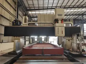
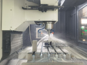
Once the mold design is approved and the steel starts moving, your mold maker will begin building, machining, and assembling the tool. This stage includes:
- CNC machining of core and cavity blocks
- Installation of runners, gates, ejector pins, and cooling channels
- Surface finishing and polishing
- Mold base assembly and alignment
Request regular updates. Ask for photos or video walk-throughs of the tool during key milestones. Confirm that critical features and tolerances are being executed as designed.
Conduct a Thorough T1 Trial
T1 means “Test One,” and it is your first opportunity to see the molded part come to life. This trial is not just about getting a part out of the machine. It is about evaluating everything.
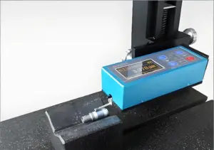
Here is what to check:
- Part dimensions versus drawing specs
- Cosmetic appearance including sink marks, flash, flow lines
- Warpage or deformation
- Gate vestige and weld line positions
- Material fill quality and cooling balance
- Mold functionality including ejection and part release
This is your best chance to catch and correct mold issues early. Some teams make the mistake of rushing past T1 to hit deadlines. That only leads to bigger problems in T2 or worse, in production.
Document Feedback and Create an Action Plan
After the T1 trial, hold a formal review session with your mold maker and internal team.
Discuss:
- What looks good and is ready to move forward
- What needs adjustment in the tool, gating, or process settings
- What changes might be required in the part design itself
Capture every issue in a clear report with photos, dimensions, and next steps. Be specific about what needs to change before the next trial.
Conclusion
That first warped part taught me something I never forgot—designing the mold is just as important as designing the part.
Now you know the steps I wish I knew then. From early planning to supplier questions, each one can save you time, money, and stress.
You don’t need to figure it out alone. You just need to start.
Ask questions. Share early. Make the mold part of your design.
So, where are you in your process? And what’s holding you back?
If you want a mold partner who gets it, contact us today. Let’s design it right the first time.
Explore Related Resources
Want to see more? We’ve gathered additional product choices to give you even more variety:
Still haven’t found what you’re looking for? Don’t hesitate to contact us. We’re available around the clock to assist you.