
I remember the first time I ordered custom metal parts for my workshop. The parts were late, didn’t fit, and I had no idea why.
That experience pushed me to learn how CNC machining actually works.
Since then, I’ve spent years working with machine shops and running a small metal fabrication business. I’ve seen what makes a job go right, or wrong.
In this guide, you’ll get a clear breakdown of the CNC process from start to finish:
- What happens at each step
- How it affects your budget and delivery
- What to check before placing an order
If you want fewer mistakes and better control, this article will help.
Let’s begin!
Step#1 Designing the CAD Model
The CNC process starts here. With your design. If the model isn’t solid, everything that comes after, cost, lead time, fit, can fall apart.
CAD stands for Computer-Aided Design. It’s a digital tool that helps you create detailed drawings or 3D models of your part.
Think of it as a virtual version of the finished product. The machine will later follow this design to cut, drill, or mill your part.
I’ve had projects stall because someone skipped a few small details in the CAD file. Missing thread info, unclear tolerances, or sharp corners that just couldn’t be milled. Every hour we spent fixing it cost us money.
You don’t want that.
Why Good CAD Matters
Your CAD file is more than just a drawing. It’s the starting point for everything. A clear model helps you:
- Avoid back-and-forth with your supplier
- Cut down on machining time
- Reduce costly rework or waste
This is where your design becomes real. It has to be right.
File Types to Use
Stick with the formats most machine shops prefer. These work well and carry full model details:
- .STEP: Good for solid models and assemblies
- .IGES: Also used for complex surfaces
- .STL: Mostly for 3D printing, but still used in CNC for simple shapes
Before you send files, double-check what your supplier accepts. It’ll save you time.
Design for Machining
Looks good on the screen doesn’t always mean easy to machine. Here’s what to watch for:
- Avoid sharp internal corners. End mills are round, so corners need a radius.
- Keep wall thickness realistic. Thin walls can vibrate or bend during cutting.
- Minimize deep holes. Deeper cuts take longer and can stress the machine.
- Use standard features. Stick to common sizes, threads, and shapes when possible.
Good design here saves hours later.
Step#2 Converting CAD to CAM
Once your CAD model is ready, the next step is turning that design into machine instructions. This step is where planning becomes action.
CAM stands for Computer-Aided Manufacturing. It’s the software used to create the actual cutting paths that the CNC machine will follow.
The CAD model shows what the part looks like. The CAM file tells the machine how to make it.
Here’s how I think about it: CAD is the blueprint, and CAM is the step-by-step guide. One shows the idea. The other shows the moves.
Why This Step Matters
This is the point where your design turns into something the machine understands. But it’s also where things can get slow, or expensive, if not handled carefully. The CAM process includes:
- Choosing tools
- Setting spindle speed and feed rate
- Planning toolpaths
- Avoiding collisions or wasted movements
Every small choice here affects how fast, smooth, and clean the cut will be.
What the CAM Programmer Does
In most jobs, CAM work is done by a skilled technician. They’ll look at your CAD file and decide:
- Which tools are best for the job
- How deep each cut should go
- In what order should the steps run
- How fast to move the tool
It’s not always automatic. Many shops still adjust toolpaths by hand, especially for complex or high-value parts.
That’s why clear CAD files, along with your notes, make a big difference. The more they understand your part, the better the result.
Best Practices for You
You may not be the one using CAM software. But you still have a role. Here’s how you can help the process go smoother:
- Stay consistent with design features. Clean models are easier to program.
- Label critical surfaces. Let the team know what matters most.
- Avoid changes after CAM begins. Updates during this stage can cause delays.
- Talk to your vendor early. If you’re unsure how your part will be made, ask before they begin programming.
Clear communication here keeps things moving and cuts down on back-and-forth.

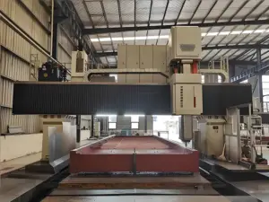
Step#3 CNC Machine Setup
Once the CAM file is ready, it’s time to prepare the machine. This is where the digital plan meets the real equipment.
Machine setup is the process of getting the CNC machine ready to cut your part. It involves choosing the right tools, loading your material, and setting positions for accurate cuts.
Even with great designs and clean toolpaths, if this step is rushed, the part won’t come out right.
I’ve seen good jobs fail just because of a poor setup. Wrong tool length. Loose fixture. Missed zero point. All avoidable, but costly when overlooked.
Key Steps in Machine Setup
Here’s what typically happens before the machine starts running:
- Tool Selection and Loading: The operator installs the tools needed for your job. These might include drills, end mills, or taps. Tool size and material must match what the part requires.
- Fixture Setup: The part needs to be held still. This is done using clamps, vises, or custom jigs. If the setup isn’t firm, the part can shift, ruining the cut.
- Zeroing the Machine: The operator sets the “home” or origin point. This tells the machine where to begin. It’s usually one corner or the center of the raw material.
- Tool Offset Calibration: Each tool is measured for length and position. These numbers are entered into the machine so it knows how deep and far to cut.
- Material Check: The right material stock is loaded, metal, plastic, or composite. The shape and size must match the job’s needs.
Each of these steps is done by a trained technician. Depending on the job, setup might take a few minutes, or a few hours.
Impact on Cost and Accuracy
Setup time adds cost. The more tools or fixtures a job needs, the longer it takes. That’s why simple designs can be cheaper to run.
If you’re ordering high volumes, the setup cost is spread out. But for small batches, it can be a big part of the price.
Also, poor setup increases the chance of scrap, delays, and machine damage. So yes, setup is behind the scenes. But it has a real impact.
Your Role in a Smoother Setup
Even if you’re not on the shop floor, your choices affect setup. Here’s how to keep things smooth:
- Limit the number of tools when possible. Fewer tool changes = faster setup.
- Design parts that sit flat or square. Easier to hold in a vise or jig.
- Avoid needing the part flipped multiple times. Every re-position adds risk and time.
- Give clear instructions about material type and stock size. That helps avoid mistakes before cutting starts.

Step#4 Programming the CNC Machine (G-Code)
Now that the machine is set up, it needs instructions to follow. This is where the G-code comes in. G-code is the language CNC machines understand. It tells the machine exactly what to do, line by line.
G-code stands for Geometric Code. It’s a set of instructions that control the movement of the machine.
Each line in a G-code file gives a clear command:
- Move here
- Cut this deep
- Use this tool
- Turn at this speed
It sounds simple. But a full program can contain hundreds, or even thousands, of lines.
I’ve seen situations where one line of code was off by a decimal point. That small mistake caused a tool to crash. It ruined the part and cost hours of rework. This is why accuracy here matters.
How G-Code Is Created
In most shops, the G-code is created automatically through CAM software. Once your toolpaths are ready, the system converts them into G-code.
But the job doesn’t stop there.
The operator or programmer usually checks the code manually or runs a simulation first. This step helps catch errors before the machine starts moving.
Sometimes, for simple jobs or repeat parts, programmers write the G-code by hand. This is common in smaller shops or when only minor edits are needed.
What G-Code Controls
The G-code file controls almost everything about the machining process:
- Cutting paths
- Feed rates
- Spindle speed
- Tool changes
- Coolant on/off
- Dwell time
Even the order of operations matters. One mistake in sequencing can lead to a bad part or even tool damage. You don’t need to write G-code yourself. But you should know what it affects.
If you ever see terms like:
- G00 or G01 – movement commands
- G02 or G03 – circular moves
- M03 or M05 – spindle start/stop
- T1 or T2 – tool numbers
These are standard parts of the G-code program. If you’re working closely with a CNC shop, it’s okay to ask how they verify the code. Some use simulators, others test-run on scrap material. Both help prevent costly errors.

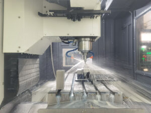
Step#5 Machining Operations Begin
Once the G-code is loaded, the real action starts. This is where the machine begins cutting your part.
The Start of Production
The operator runs a final check, tools in place, material secured, and program ready. Then the machine starts following the code step by step.
Each tool does its job:
- Drills make holes
- End mills shape edges and pockets
- Taps cut threads
- Cutters slice or trim material
You can often hear the rhythm change as the tool switches or the speed adjusts. That sound means the program is moving forward.
I remember one job where the part looked simple, but the cutting took hours. The material was hard, and the tolerances were tight. We had to slow things down just to keep them right.
Production isn’t always fast. But it’s always precise, if everything’s set correctly.
Types of Machining Processes
Your part might go through several operations, depending on its design:
- Milling: Removes material using rotary tools. Great for flat surfaces, pockets, and angled cuts.

- Turning: Used on lathes to shape round parts. The material spins while the tool stays still.

- Drilling: Creates holes using drill bits. Often used with milling or turning.

- Tapping: Cut internal threads inside holes.

- Boring: Enlarges holes that need very tight tolerances.

- Facing: Creates a smooth, flat surface, usually the first step on raw material.

Each operation follows a set order. Rough cuts first. Finishing passes last.
What Affects Time and Cost
This step is where a lot of your money is earned, or wasted. Here’s what adds time:
- Small tools (need more passes)
- Deep cuts (slower speeds)
- Hard materials (more wear on tools)
- Tight tolerances (require slower, finer cuts)
If you’re ordering in small batches, expect more machine time per part. For larger runs, that time spreads out.
Also, any mistake here, like like tool breaking or material shifting, can ruin the part. That’s why skilled operators monitor every run closely.
Ask or Watch For
Even if you’re not on-site, it helps to know:
- How long is the cycle time
- What types of tools are used
- Whether the part is cut in one setup or needs flipping
- If any parts are scrapped during the first run
This shows how stable the process is, and how repeatable it will be at scale.
Step#6 Post-Processing
After machining is finished, the part isn’t ready to ship just yet. There are still final touches needed to meet the right appearance, function, and safety.
Post-processing includes all the work done after the part is cut. It’s where the raw edges are cleaned up, the surfaces are smoothed, and any special finishes are added.
Even if the machining is perfect, the part might have sharp edges, tool marks, or oil from the cutting process.
I’ve handled parts straight off the machine that looked okay, but still needed several hours of finishing. That’s normal. This step makes sure the part is truly complete.
Common Post-Processing Steps
Depending on your needs, post-processing may include:
- Deburring: Removes sharp edges or leftover metal bits. Often done by hand or with brushes and tumblers.
- Surface Finishing: Improves the appearance or texture. Can involve sanding, polishing, or bead blasting.
- Cleaning: Removes coolant, oils, or dust from machining. May involve water, solvents, or air.
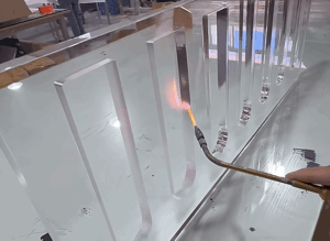
- Heat Treatment: Makes metal stronger or more durable by changing its internal structure with heat.
- Coating or Plating: Adds a protective or decorative layer. Common types include anodizing, powder coating, or zinc plating.
- Marking or Labeling: Add serial numbers, logos, or other IDs. Often done by laser or stamping.
Not every job needs all of these. It depends on the part, material, and use case.
Why It Matters
Skipping post-processing can cause serious problems.
Parts may look rough, fit poorly, or wear out faster. Worse, they could injure someone during use.
If you’re making a part for end use, or that fits with another component, post-processing is critical. Even small changes in surface finish or size can affect how the part performs.
What You Can Do
Here’s how to plan ahead for this step:
- Ask what’s included. Not all suppliers include finishing by default.
- Be clear about requirements. Surface texture? Edge radius? Coating type? List it in the RFQ or drawing.
- Consider the impact on size. Some finishes add thickness. Make sure that’s factored in.
- Talk about packaging. Finished parts can scratch easily. Check if they’ll be bagged, boxed, or wrapped.
Step#7 Quality Inspection
Before a part is packed and shipped, it goes through one last step: inspection. This is where we make sure everything meets the specs.
Even with great tools, machines, and setups, things can go wrong.
Tools wear down. Materials shift. A wrong offset can cause a size to be slightly off. Without inspection, you wouldn’t catch these issues until it’s too late.
In my shop, we’ve caught issues in final checks that saved a project. Once, a part was just 0.2 mm out of one hole. Small miss, but it wouldn’t fit the assembly. Fixing it early kept us from missing the delivery.
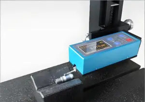
What the Inspection Covers
Quality checks vary depending on the part and its purpose. But they often include:
- Measuring Part Dimensions: Using calipers, micrometers, or CMM (Coordinate Measuring Machines) to check against drawings.
- Verifying Tolerances: Making sure each feature falls within the allowed size range.
- Surface Inspection: Checking for scratches, dents, or finish problems.
- Thread and Hole Checks: Confirming hole sizes, depths, and thread quality.
- Fit Tests: If your part mates with another, some shops do test fits before shipping.
At MachMaster, we take this seriously. Every CNC part that goes out is inspected. Our team reviews critical dimensions and features before the part is cleared for delivery. It’s part of our process, not an afterthought.
Benefits
Good inspection means:
- Fewer rejected parts
- Less time spent on returns or rework
- More confidence in every shipment
For larger orders or tight specs, we also recommend asking for an inspection report. This is a document that lists what was measured and the actual results.
It gives you full traceability and peace of mind.
Conclusion
We started with a story about frustration. Now, you’ve got the knowledge to change the outcome. CNC machining doesn’t have to be a mystery, it just takes the right guide and the right partner.
From design to delivery, Machmaster’s got your back. They’ll help you cut waste, trim lead times, and get perfect parts every time.
You’ve read the how. You’ve seen the why. The next step is yours.
Are you ready to level up your machining game?
Let’s make your next order your best one yet.
Contact us today and take control of your next project with us by your side.