
What Is Surface Roughness?
Surface roughness describes the small irregularities on a machined surface. Even when a CNC machined part looks smooth, its surface still has tiny peaks and valleys.
These variations can affect how parts fit together, move against each other, seal, or resist wear. That’s why surface roughness is often included as a requirement on engineering drawings.
For CNC machined parts, the required finish depends on the part’s function. A mounting surface, sliding contact area, and non-functional outer surface may not need the same level of smoothness.
Surface Roughness Chart: Ra, Rz and N Grades
Surface roughness is commonly specified using parameters such as Ra and Rz. Engineering drawings may also use N grades to indicate a required surface finish.
Ra Surface Roughness Chart
Ra (Roughness Average) measures the average deviation of a surface profile from its mean line over a sampling length. It is one of the most commonly used surface roughness parameters in manufacturing.
| N Grade | Ra (μm) | Ra (μin), Approx. |
|---|---|---|
| N1 | 0.025 | 1 |
| N2 | 0.05 | 2 |
| N3 | 0.1 | 4 |
| N4 | 0.2 | 8 |
| N5 | 0.4 | 16 |
| N6 | 0.8 | 32 |
| N7 | 1.6 | 63 |
| N8 | 3.2 | 126 |
| N9 | 6.3 | 250 |
| N10 | 12.5 | 500 |
| N11 | 25 | 1000 |
| N12 | 50 | 2000 |
Note: These are commonly used nominal Ra values associated with N grades. Actual drawing requirements and applicable standards should always be checked.
Ra vs. Rz: What’s the Difference?
Ra and Rz describe surface texture in different ways.
- Ra: The arithmetic average of the absolute profile deviations from the mean line. It gives an overall indication of surface roughness.
- Rz: A measure based on the peak-to-valley height of the surface profile over specified sampling lengths. The exact calculation depends on the measurement standard.
Ra is widely used for general surface finish specifications. Rz can provide additional information when peak-to-valley characteristics are important.
Ra and Rz are not directly interchangeable. If a drawing specifies one parameter, a supplier should not assume that another parameter with a seemingly equivalent value will meet the requirement.
Surface Roughness Symbols on Engineering Drawings
Surface texture symbols tell the manufacturer what surface condition is required. Understanding these symbols helps avoid confusion during quoting and production.
Common surface texture symbols include:
- Basic surface texture symbol: Indicates a surface texture requirement without specifying the manufacturing method.
- Symbol with a bar: Indicates that material removal is required, such as machining.
- Symbol with a circle: Indicates that material removal is not permitted.
A drawing may also include additional information such as Ra value, machining allowance, sampling length, or the required manufacturing process.
For example, a drawing may specify Ra 1.6 μm on a machined face. This means the specified surface must meet that roughness requirement, not simply look smooth to the eye.
When reviewing a drawing, check the symbol, parameter, value, and the specific surface to which the requirement applies.
What Affects Surface Roughness in CNC Machining?
The final surface finish depends on more than the CNC machine itself. Several factors influence the result.
1. Cutting Tool Condition
A sharp, suitable cutting tool generally produces a more consistent surface. Worn or damaged tools can leave visible marks, scratches, or irregularities.
2. Cutting Parameters
Cutting speed, feed rate, and depth of cut all influence surface quality. The right combination depends on the material, tool geometry, and machining operation.
3. Material Properties
Different materials respond differently to cutting. Aluminum, stainless steel, brass, and engineering plastics may require different tooling and machining parameters to achieve the required finish.
4. Machine Vibration and Workholding
Vibration during machining can leave visible patterns or uneven surface marks. Stable workholding and suitable machining conditions help maintain consistency.
5. Coolant and Chip Removal
Appropriate coolant use and effective chip removal can help reduce heat buildup, prevent chip interference, and improve the consistency of the machined surface.
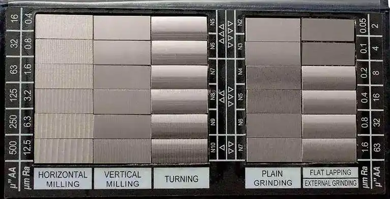
Typical Surface Roughness Requirements for CNC Parts
Not every surface on a part needs the same roughness level. The appropriate requirement depends on how the surface functions.
| Part Surface or Application | Typical Consideration |
|---|---|
| General machined surfaces | A standard machined finish may be sufficient |
| Mating surfaces | Surface finish should support proper fit and contact |
| Sliding or moving surfaces | Roughness may affect friction and wear |
| Sealing surfaces | Surface texture should suit the sealing method |
| Visible exterior surfaces | Appearance and consistency may be important |
| Precision contact surfaces | Requirements should be defined clearly on the drawing |
These are general selection considerations, not universal Ra specifications. The actual value should be determined by the part’s function, material, design, and assembly requirements.
How to Specify Surface Roughness for CNC Machined Parts
When preparing a drawing for CNC machining, it helps to specify surface roughness according to the function of each surface.
Here are a few practical points:
- Identify functional surfaces: Focus on areas involved in sealing, sliding, fitting, or precise contact.
- Avoid unnecessary requirements: Applying a very low Ra value to every surface can increase machining time and cost without improving part performance.
- Use clear drawing symbols: Specify the required parameter and value, and identify which surfaces the requirement applies to.
- Clarify additional finishing: If a part needs anodizing, polishing, blasting, or another finishing process, make sure the drawing distinguishes the required final condition from the machined surface requirement.
- Confirm inspection expectations: If a particular surface is critical, identify the inspection location and any reporting requirements.
Clear specifications help the manufacturer select suitable machining and inspection methods before production begins.
How Is Surface Roughness Measured?
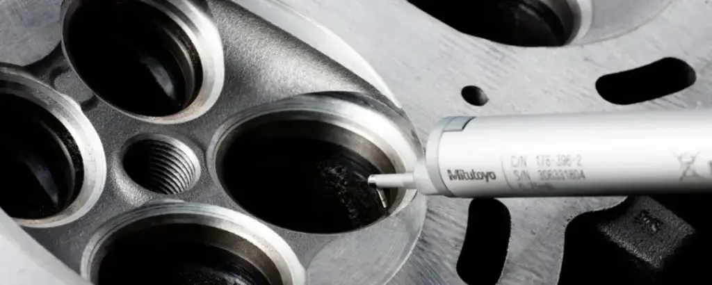
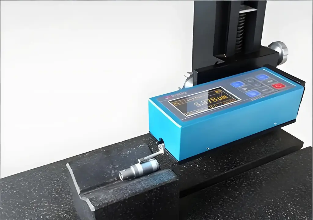
Surface roughness is commonly checked using a surface roughness tester, also called a profilometer.
Contact-Type Measurement
A contact-type tester uses a small stylus that travels across the surface. It records the surface profile and calculates parameters such as Ra and Rz.
This method is widely used for checking machined metal surfaces.
Non-Contact Measurement
Non-contact systems use optical methods to measure surface topography without touching the part. They may be useful for delicate surfaces or applications where stylus contact is unsuitable.
Choosing the Measurement Location
The measurement location matters. The tester should be used on the surface identified by the drawing, with an appropriate measurement direction and evaluation setting.
For machined surfaces with visible tool marks, the measurement direction may affect the result. Inspection should follow the applicable standard and the drawing requirements.
Common Applications of Surface Roughness Control
Surface finish requirements vary across industries and part designs.
- Automotive components: Mating, bearing, and contact surfaces may need controlled roughness to support fit and performance.
- Industrial machinery: Sliding and moving components may require suitable surface texture to manage friction and wear.
- Hydraulic and pneumatic parts: Sealing surfaces and precision interfaces may need specific finish requirements.
- Electronic enclosures: Exterior surfaces may place more emphasis on appearance and finishing consistency.
- Molds and tooling: Surface texture can influence the finish of the products made with the tooling.
The important point is to specify the finish according to the part’s actual function rather than applying the same requirement to every surface.
CNC Machining with Specified Surface Finish at Machmaster
Machmaster provides custom CNC machining for components made from aluminum, stainless steel, brass, and other common engineering materials.
With 40+ CNC machining machines, CNC milling and turning capabilities, and ISO 9001:2015 quality management, we support custom parts from prototype orders to larger production runs.
Our inspection equipment includes a surface roughness tester, VMM, micrometers, height gauges, and other conventional measuring tools. Inspection requirements and documentation can be discussed according to your project.
We also offer finishing options, including in-house anodizing, to help customers coordinate machining and finishing requirements.
If your drawing specifies Ra, Rz, or an N-grade surface finish, send us your drawings and requirements. Our team can review the specifications and help you confirm a suitable manufacturing approach.
Need CNC machined parts with specific surface finish requirements? Contact Machmaster to discuss your project and request a quote.