
Back when I first started working with shaft parts machining, I stood by an old lathe, hands sweaty, hoping I wouldn’t screw up. I didn’t even know what a simple taper was.
That’s how clueless I was in the beginning.
I learned the hard way. I asked tons of questions, watched skilled machinists run their tools like artists, and yes, I messed up more times than I care to admit.
That’s why you can trust me here. I know exactly what it’s like to start from zero and try to figure this all out.
You’re probably reading this because you want a simple, honest way to see how shaft parts are machined.
Whether you own a shop, design products, buy parts, or just want to learn for your own projects, I’ve got you covered.
This guide will show you each step from turning, grinding, measuring and why it matters.
By the end, you’ll have a clear picture of the whole process. You’ll be able to look at a shaft and actually understand what went into making it.
So let’s get started!
Quick Guide
Before we go deep into each process, here’s a quick snapshot of the full machining journey. This table gives you a clear view of what’s coming.
| Steps | What to Do |
| Step#1 Material Selection and Preparation | Cut the raw bar to size, clean off dirt or rust, and label each piece clearly. |
| Step#2 Facing and Center Drilling | Face one end flat and drill a shallow center hole to support the shaft during turning. |
| Step#3 Rough Turning | Remove most of the excess material and shape the shaft close to its final dimensions. |
| Step#4 Finish Turning and Grooving | Take light, precise passes to reach final size and cut any needed grooves. |
| Step#5 Keyway or Spline Machining | Cut a keyway or spline to let the shaft lock with gears, pulleys, or other parts. |
| Step#6 Threading and Drilling Operations | Drill holes and cut threads with steady pressure and correct alignment. |
| Step#7 Heat Treatment (Optional) | Strengthen the shaft with heat based on its use; handle carefully after. |
| Step#8 Grinding and Final Inspection | Grind the surface smooth, check all measurements, and clean it up for final use. |
Now that you’ve got the big picture, let’s walk through each step in detail.
Step#1 Material Selection and Preparation
This is the part many people overlook but I learned not to. I once spent half a day machining a shaft that twisted on the test rig. Wrong steel, wrong prep. That mistake still sticks with me.
Getting the right material and preparing it properly will save time, tools, and scrap.
Choose the Right Shaft Material
- Use 1018 Mild Steel for Low-Stress Shafts: Cut this steel to rough length using a bandsaw, leaving extra room for cleanup. Mount it securely during turning to avoid chatter, as the material is soft.
- Use 4140 or 4340 Alloy Steel for Strength Jobs: Cut with a sharp blade and apply cutting oil to avoid overheating. Rough turn it before heat treating if needed to reduce stress buildup.
- Use 303 or 316 Stainless Steel for Corrosive Environments: Cut slowly to avoid hardening the surface and clean the cut ends with acetone right away. File the edges smooth to protect your chuck jaws.
- Use 6061 Aluminum for Lightweight Applications: Cut the aluminum slowly with proper clamping to avoid burring. Use a file or deburring tool immediately after to prep it for setup.
- Avoid Using Unmarked or Mixed Scrap: Discard bars with unknown grade or visible wear. Machining this kind of material wastes time and may damage tooling.
Cut the Material to Rough Length
- Use a Bandsaw or Cold Saw to Cut Blanks: Measure the part and add 3–5 mm of extra length before cutting. This allows room for facing and cleanup cuts during machining.
- Keep Cuts Square With Proper Saw Alignment: Adjust the vise and blade before each cut to maintain squareness. A flat cut helps the part seat properly in the chuck.
- Label Each Piece With a Marker: Write the material grade directly on the blank after cutting. This helps keep jobs organized, especially when working with similar-looking metals.
- Deburr the Ends With a Hand File: File the sharp edges to avoid damaging the chuck and to make clamping more stable. This also keeps fingers safe during handling.
- Lay Cut Stock Flat on a Clean Surface: Place each blank on a table or rack to prevent bending. Avoid stacking them unevenly, especially when they’re still warm from cutting.
Clean and Inspect the Material
- Wipe the Bar With Acetone or Cleaner: Use a rag and solvent to remove oil and dirt from the surface. A clean part prevents tool slip and gives better finish results.
- Remove Rust With a Wire Brush or Grinder Wheel: Scrub the surface evenly before mounting in the machine. This keeps the insert sharp and avoids poor surface cuts.
- Check for Warping by Rolling on a Flat Table: Roll the blank to look for wobble or unevenness. Set aside any bars that show visible bends.
- Deburr Edges Using a Chamfer Tool: Rotate the tool along the outer edge of the cut face to create a clean bevel. This helps the chuck grip better and improves tool access.
- Scribe a Center Mark if Using Manual Setup: Use a caliper or center finder to mark the middle of the face. This saves time during lathe setup and reduces adjustment errors.
Once the material is chosen, cut, and cleaned, you’re finally ready to start shaping it. At MachMaster, this step is focused and deliberate. A solid start sets the pace for everything that follows and they never rush the foundation.

Step#2 Facing and Center Drilling
Once the material is cut, cleaned and ready, the next move is getting it on the lathe for facing and center drilling. This is where machining actually starts and it’s also where small mistakes can snowball. I’ve learned that a crooked face or an off-center hole throws off every cut after this.
A clean face and centered hole are what allow the rest of the shaft to run true. So take a minute. Do it right.
Face the Shaft End Flat and Square
- Mount the Stock Firmly in the Chuck: Tighten the jaws evenly and use a dial indicator to confirm the shaft runs straight. Poor grip here leads to bad cuts later.
- Bring the Tool to Lightly Touch the Face: Feed in slowly until the tool just contacts the material. Set zero on the DRO or dial once contact is made.
- Take a Light Cleanup Pass Across the Face: Move the tool smoothly from center to outer edge. This gives you a true, flat surface to work from.
- Make a Second Pass If Needed: If the full face isn’t clean after the first pass, take off a little more. Don’t force the tool, this step is about precision, not speed.
- Break the Edge With a Chamfer Tool or File: Lightly touch the outer rim to remove burrs. This helps with handling and improves chuck seating on the next setup.
Drill a Center Hole for Later Support
- Install a Center Drill in the Tailstock Chuck: Lock it in securely and align it with the part’s center. A centered hole helps keep the shaft stable during future turning.
- Run the Lathe at Low Speed While Advancing the Drill: Use a slow feed to avoid tool bending or walking. Keep cutting fluid applied to control heat.
- Drill Just Deep Enough to Seat the Live Center: Watch for the conical shape to form, this is where your tailstock center will sit. No need to drill deep.
- Retract the Drill and Clean the Hole: Use a brush or compressed air to remove chips. A clean center gives smoother rotation support.
- Check the Center Hole Visually Before Proceeding: If it’s not straight, re-cut now. It’s a small step that saves major issues later.
With a clean face and accurate center hole, the shaft is finally ready to take shape.
Step#3 Rough Turning
Now that the shaft has a clean face and a center hole, it’s time to shape the outside. Rough turning is where things finally start to look like a real part. This step is all about removing material quickly, getting close to the final size but not all the way there.
I used to worry a lot during this step. My first few tries left the surface rough, and I panicked about tool marks. What I didn’t realize back then was that rough turning isn’t about perfection, it’s about getting close and keeping things stable.
Set Up for a Stable Rough Cut
- Support the Shaft With a Live Center: After clamping the part in the chuck, bring the tailstock up and lock the center into the drilled hole. This keeps the shaft from flexing during long passes.
- Use a Rigid Tool and Proper Insert: Mount a roughing tool with a strong cutting edge. A sharp, positive-rake insert works best for heavy cuts.
- Set RPM Low to Moderate: Keep the speed reasonable to avoid vibration. Rough cuts don’t need high spindle speed, just steady feed and control.
- Use Consistent Depth per Pass: Start with 1–2 mm cuts and adjust based on material. Avoid aggressive cuts that can deflect the shaft.
- Apply Cutting Fluid if Needed: Use coolant to reduce heat and extend tool life, especially with harder materials like 4140 steel.
Turn Down to Near Net Shape
- Take Multiple Passes to Remove Bulk Material: Begin from one end and work in steady passes until most excess material is gone. Check the diameter after every few cuts.
- Leave Around 0.3–0.5 mm for Finishing: Stop once you’re close to final size. That small leftover layer gives room for precision cuts later.
- Check for Taper Along the Shaft: Use calipers or a micrometer at both ends to catch early signs of uneven cutting. Adjust tool pressure if needed.
- Watch for Tool Chatter or Vibration: If the surface starts looking wavy or noisy, pause and adjust speed or support. That’s usually the shaft telling you something’s off.
- Clean Chips Regularly During Cutting: Use a chip hook or air blast to clear the tool path. Clean work keeps the cut consistent.
Rough turning is where the shaft finally starts to take form and where you start feeling like you’re building something real. It doesn’t have to be perfect here, just solid and even.
Step#4 Finish Turning and Grooving
After rough turning, the shaft has its basic shape but it’s still not ready. This next step is precision. A wrong groove width or an extra 0.1 mm in diameter can cause the whole part to fail. That’s something I had to learn the hard way, more than once.
Finalize the Shaft Diameter
- Install a Sharp Finishing Insert: A clean edge leaves a smoother finish. This helps reduce friction when the shaft runs inside a bearing.
- Set the Tool Exactly on Center: Use a shim or tool setter to make small adjustments. Being slightly off can cause tapered cuts or chatter.
- Take Light, Consistent Passes Until Final Size Is Reached: Cut around 0.2 mm at a time and stop between passes to check size. A micrometer gives better readings than calipers at this stage.
- Adjust Feed Rate for Smoother Finish: Slower, steady feeds help prevent lines or ridges. That little change can make the part look and perform better.
- Break the Edges Gently With a File or Chamfer Tool: A smooth corner avoids cuts during handling. I’ve sliced a finger more than once on a sharp, fresh-cut edge.
Add Grooves or Shoulders as Needed
- Set the Groove Location With a DRO or Handwheel Scale: Double-check positions before cutting. Even being off by half a millimeter can cause assembly issues.
- Use a Matching Grooving Tool for the Width Required: Choose the right size so the tool doesn’t deflect. Narrow tools break easily, learned that one from a snap mid-cut.
- Make Multiple Light Passes for Deeper Grooves: Cut a little, then back out to clear chips. Forcing deep cuts all at once often ruins the edge.
- Measure Groove Depth and Width After Each Pass: Use a groove mic or depth gauge. Better to stop early and trim than go too far and lose the part.
- Clean the Groove With Fine Emery Cloth for a Smoother Fit: Wrap the cloth around a flat stick and gently polish the sides. This helps mating parts seat without resistance.
This is the step where rough work turns into real precision and where experience really starts to show in the details. A shaft that’s sized right, clean, and grooved where it needs to be makes the rest of the build easier for everyone.

Step#5 Keyway or Spline Machining
After the shaft is turned, sized, and grooved, it’s ready for one of its most important jobs, transferring torque. That’s where keyways and splines come in. These features lock the shaft into gears, couplings, or pulleys and keep everything moving together.
I had a keyway job early on that looked fine on the drawing. But the slot ended up too wide just by a fraction and the key kept rocking during testing. I didn’t want to remake the whole part, but in the end, I had to. Since then, I treat this step with a lot more care.
Cut the Keyway with Precision
- Set Up the Shaft in a Mill or Broaching Fixture: Secure the part using a vise or keyway jig. Align the shaft carefully to make sure the slot runs straight.
- Use an End Mill or Broach That Matches the Key Size: Select a standard width cutter like 3 mm or 6 mm. Avoid forcing the tool into tight fits.
- Cut in Small Steps to Reach the Desired Depth: Lower the cutter slowly and clear chips between each pass. Cutting too deep in one go can throw the alignment off.
- Measure Keyway Width and Depth After Each Pass: Use calipers or a depth micrometer to stay on track. Small errors add up fast here.
- Deburr the Keyway Edges With a Small File: Clean the slot gently to remove burrs. This helps the key seat without binding.
Machine Splines for Higher Torque Applications
- Mount the Shaft in a Spline Indexing Fixture or CNC Setup: Use a dividing head or spline jig to index the shaft evenly. Precise rotation ensures consistent spacing between teeth.
- Select the Correct Cutter Based on Spline Type: Choose an involute spline cutter that matches the drawing. Each spline shape has specific depth and pressure angles.
- Make Repeated Light Passes for Each Tooth: Take shallow cuts to keep the spline form accurate. Rushing this step often leads to distorted profiles.
- Check Tooth Spacing and Fit With a Gauge or Mating Part: Fit the shaft with a sample gear or coupling to confirm alignment. It’s better to spot problems here than later during assembly.
- Polish the Machined Spline Lightly With Emery Cloth: Smooth the flanks and remove burrs. This helps reduce wear when parts engage under load.
I have to be honest, this step still makes me slow down more than usual. Even now, after years of machining, I double-check the setup every time. When the shaft locks in and runs smooth on the first try, it’s one of those quiet wins that feels good.

Step#6 Threading and Drilling Operations
At this point, the shaft already looks nearly complete. But it still needs fine features like drilled holes and threads, things that may not take long, but can cause big problems if done wrong.
I’ve watched others ruin good parts by pushing a dull tap or forgetting to clear chips. Sometimes, the smallest steps can undo the most time-consuming ones.
Create Accurate Holes
- Clamp the Shaft Securely Before Drilling: Use a solid vise or fixture. Movement during drilling is one of the most common causes of hole misalignment.
- Spot the Hole With a Center Drill First: This small cone helps the twist drill start straight. Skipping it often leads to wandering bits.
- Drill in Short Increments and Clear Chips Frequently: Pull out every few seconds, especially on deeper cuts. Chip buildup can cause overheating or deflection.
- Mark the Depth on the Drill Bit With Tape: Use a simple tape flag to stop at the right depth. No need to guess, or go too far.
- Deburr the Hole Using a Chamfer Tool: A smooth edge not only looks better but prevents damage when inserting fasteners later.
Cut Clean Threads
- Tap by Hand With Steady, Vertical Pressure: Keep the tool square using a guide or tapping block. A slight tilt can mess up the entire thread path.
- Back the Tap Out Often to Break Chips: Turn in, then reverse a half-turn. This clears debris and avoids clogging.
- Apply Cutting Fluid Generously Throughout the Process: Lubrication matters. It keeps the tap cooler and the thread cleaner.
- Brush Out the Finished Thread Before Testing Fit: Loose chips inside the thread can make even a perfect cut feel tight.
- Test the Thread With a Mating Bolt or Thread Gauge: This final check confirms that everything fits as intended. It’s a small moment that saves a lot of future problems.
Threading and drilling feel like small tasks compared to rough turning or spline machining, but they’re often where parts pass or fail. Sometimes I don’t even breathe while tapping, just because I’ve seen what happens when a tool snaps deep in a finished shaft.

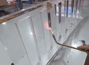
Step#7 Heat Treatment (Optional)
After all the drilling, threading, and shaping is complete, some shafts still need one last thing, strength. That’s where heat treatment comes in.
There was a batch I worked on that passed inspection right after machining, but bent after the first real load. The material was fine, the cuts were clean but no heat treatment. It didn’t fail right away. It just gave out quietly under pressure.
Prepare the Shaft for Heat Treatment
- Clean Off Oils and Cutting Fluid: Wipe down the shaft thoroughly before heat treating. Residue on the surface can leave marks or cause uneven hardness.
- Double-Check Dimensions and Allowance: Make sure enough stock is left if grinding comes after. Heat treatment can cause slight distortion.
- Mark or Tag the Shaft Clearly: Use a punch or high-temp marker to label the part. Labels help avoid confusion when multiple parts go in together.
- Choose the Correct Heat Treatment Method for the Material: Use quenching and tempering for 4140, or solution treating for stainless, depending on spec.
- Package the Shaft Properly for Off-Site Processing: If sending to a heat treat shop, protect the surfaces from impact. A well-machined shaft can still get dinged in a box.
Handle Post-Treatment Distortion and Finish
- Inspect the Shaft for Straightness Right After Heat Treatment: Use a dial indicator or spin it between centers. Warping is common, even in well-controlled cycles.
- Straighten Light Warps Using a Press or Fixture: Minor bends can often be corrected with light force. Do this before final grinding.
- Leave the Shaft to Cool Slowly if Allowed by Spec: Avoid rapid cooling unless required, some steels benefit from a slower cool-down.
- Document Hardness Using a Rockwell or Brinell Test: Take a quick reading and record the result. It confirms the treatment did what it was supposed to.
- Move Quickly Into Grinding or Finish Work if Needed: Don’t wait too long. Treated surfaces can oxidize or get scratched if left sitting around.
Heat treatment always feels like sending your part through something unknown, it disappears for hours (or days) and comes back looking the same, but totally changed inside. I’ve had parts come back harder, stronger, but also slightly warped. That’s just part of the tradeoff.

Step#8 Grinding and Final Inspection
After heat treatment, the shaft may look finished but it’s not ready yet.
That hard surface needs a final cut. Grinding smooths out any warping, removes leftover material, and brings the shaft down to its exact size. Then comes inspection, where every dimension and surface is checked to make sure the part actually meets spec.
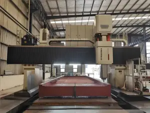
Finish the Shaft Surface With Precision Grinding
- Mount the Shaft Between Centers or in a Steady Rest: Use soft pads or dead centers to avoid marring the ends. Make sure everything runs true before starting the wheel.
- Dress the Grinding Wheel Before Each Job: Use a diamond dresser to clean and true the wheel. A fresh surface gives better finishes and tighter tolerances.
- Take Light Passes, Especially After Heat Treatment: Remove small amounts at a time to avoid overheating. Hardened shafts can crack under too much pressure.
- Check the Diameter After Each Pass Using a Micrometer: Don’t trust the DRO alone, heat can expand the part slightly. Mic readings help catch that.
- Apply Coolant Steadily Throughout the Grind: Keep the part cool and the surface clean. A dry cut might look fine, but could burn the steel.
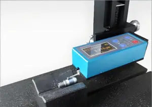
Inspect the Shaft for Accuracy and Surface Quality
- Use a Dial Indicator to Check for Runout: Mount the shaft and rotate it slowly. A slight wobble here shows problems with chucking, warping, or uneven grinding.
- Measure All Critical Diameters With a Micrometer: Focus on bearing seats, shoulders, or spline fits. Even one missed dimension can cause assembly failure.
- Check Surface Finish With a Fingernail or Surface Comparator: Feel for rough spots, scratches, or grinding marks. They can wear out mating parts fast.
- Look Over Grooves, Threads, and Keyways: Make sure everything is clean and free of burrs. Sometimes it’s the smallest features that get overlooked.
- Document Measurements Before Approving the Part: Write down all key sizes and tolerances. This record gives traceability and helps catch patterns in future runs.
Grinding and inspection might not sound exciting, but it’s where all your hard work either holds up or falls short. For me, it’s the moment when the part becomes real, finished, checked, and ready to be used.
At MachMaster, they bring that same care to every job. They don’t just make parts; they stand behind them. From one-offs to full production runs, they’re always ready to support makers who care about getting it right.
Conclusion
So, we walked through how shafts get turned, ground, and measured.
It’s not magic, it’s skill, patience, and the right steps.
I started nervous by that old lathe.
Now, I see each shaft as proof of what practice can do.
The hard part? Getting started. But you’re closer than you think.
Ready to bring your shaft project to life?
Contact MachMaster today. We’ve helped hundreds of builders just like you and now it’s your turn!