
The first time I handled surface roughness specs on a drawing, I googled “Ra” in a panic. I wasn’t alone. Our supplier had done the same.
Since then, I’ve learned just how critical surface roughness is to fit, function, and even corrosion resistance.
This article is the resource I wish I had back then. Written for teams in the trenches like engineers, buyers, and QC leads, it’s based on years of hands-on work.
We’ll go over roughness parameters, industry standards, measurement tools, and when surface finish can make or break your build. By the end, you’ll know exactly how to handle roughness in specs, sourcing, or troubleshooting.
If you’ve ever nodded along pretending you knew what “32 microinch” meant, this is for you.
Let’s get started!
1. What Is Surface Roughness?
Surface roughness refers to the small, finely spaced surface irregularities that form as a result of the manufacturing process.
It’s measured in terms of the vertical deviations of a surface’s profile, typically using micrometers (μm) or microinches. The rougher the surface, the higher the number.
And here’s the catch:
Surface roughness is different from surface texture and surface finish. Roughness is just one component. It specifically measures the tiny peaks and valleys that remain after machining, grinding, or casting.
It’s not just cosmetic, it affects how your product performs in the real world.
Whether you’re working in aerospace, automotive, or precision tooling, roughness plays a critical role in your final product. Once I understood that, I started paying a lot more attention to those squiggly lines on drawings.
2. Why Surface Roughness Matters
If you’ve ever had parts seize, leak, or vibrate, there’s a good chance surface roughness was part of the problem. I once watched an o-ring fail in a hydraulic assembly just because the groove surface was too rough. It didn’t just leak. It burst under pressure.
That’s the thing about roughness. It might be invisible to the naked eye, but it controls a lot behind the scenes. Here are just a few reasons it matters:
- Friction and Wear: The smoother the surface, the less friction it creates. But if it’s too smooth, you lose the grip needed for certain functional fits.
- Lubrication Retention: A slightly rough surface helps hold lubricants in place, especially under motion. If the surface is too rough, it will break the lubricant film and increase wear.
- Sealing Performance: Seals work best when the surface allows uniform contact. If the finish is too rough or too smooth, it can cause leaks and reduce sealing pressure.
- Coating and Plating: Textured surfaces improve adhesion for paints or plating layers. However, they also require more coating material to cover the surface evenly.
- Fatigue Resistance: Tiny valleys on the surface can act as stress risers under repeated loading. These spots often become the starting point for cracks and fatigue failure.
Ultimately, surface roughness is more than just a detail in a drawing. It’s a functional spec that can determine whether your part performs well or causes costly problems.

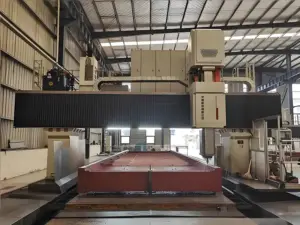
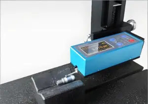
3. How Surface Roughness Is Measured
The first time I saw a surface roughness tester in action, I was surprised by how delicate it looked. There’s more than one way to measure roughness, and the method you choose can affect cost, accuracy, and even how results are interpreted. Let’s break it down into three practical categories you’re likely to encounter.
Contact Profilometers
This is the most common method, and I’ve used it on everything from shaft finishes to machined molds. A small stylus traces along the surface, capturing peaks and valleys to calculate a roughness profile.
It gives you reliable values like Ra and Rz and is ideal for flat or accessible surfaces.
But it does have limitations: soft materials can be damaged by the stylus, and complex shapes can be hard to reach.
Still, if you’re working with a standard machine shop, this is probably what they’re using. It’s cost-effective, proven, and easy to train someone on.
Non-Contact Optical Methods
I remember testing a polished aluminum part using a laser scanner, and the results were surprisingly detailed. These non-contact tools use lasers or light to build a 3D map of the surface without ever touching it.
That’s a big win for delicate, curved, or very small parts where a stylus might distort the surface. These methods include confocal microscopy, white light interferometry, and laser triangulation systems.
They’re fast and incredibly accurate, but they do come with higher upfront cost and require a more controlled lab environment. If your parts are critical and high-value, it’s often worth the investment.
Visual and Tactile Comparators
Sometimes, you just need a quick check. I’ve kept a set of comparator plates in my toolbox for years. They don’t give you numbers, but they help you feel what a Ra 3.2 vs Ra 0.8 finish looks like.
These tools use machined samples to give you a physical reference point. They’re great for shop-floor checks, early-stage prototyping, or when you don’t need a formal inspection. The downside is they’re subjective and can lead to inconsistent interpretation. But when paired with experience, they offer fast, practical feedback.

4. Surface Roughness Standards and Symbols
Understanding surface finish symbols and standards used across regions can save you from costly misunderstandings. This table gives you a quick reference to what each value, symbol, and designation means in practice.
| Symbol/Code | Meaning | Typical Use Case | Standard Reference | Roughness Value (Ra) |
| Ra | Roughness Average – measures mean deviation | Most common roughness spec on drawings | ISO 4287, ASME B46.1 | e.g. Ra 1.6 μm or Ra 63 μin |
| Rz | Average maximum peak-to-valley height | Used in sealing, wear-critical applications | ISO 4287 | Often 4–5x higher than Ra |
| Rq | Root mean square deviation | Emphasizes larger peaks/valleys more than Ra | ISO 4287 | Similar to Ra but more sensitive |
| ⌝ (Basic Symbol) | Indicates surface texture requirement | Applied to any surface that needs control | ISO 1302 | Must be accompanied by a value |
| ⌝ with number | Specifies surface roughness value | e.g. ⌝ 3.2 means Ra 3.2 μm required | ISO 1302 | μm (metric) or μin (imperial) |
| ⌝ with bar | Material removal required | Indicates a machined surface | ISO 1302 | Often used for CNC or turned parts |
| ⌝ with circle | No material removal allowed | As-cast, as-forged, or as-formed surfaces | ISO 1302 | Used in near-net-shape designs |
| N1 – N12 | Surface finish grades (ISO/old DIN scale) | Common in global or legacy drawings | ISO 1302 / DIN 476 | N1 = 0.025 μm to N12 = 50 μm |
| CLA (μin) | Center Line Average in microinches | U.S. customary version of Ra | ASME B46.1 | e.g. CLA 125 μin = Ra 3.2 μm |
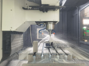
5. Factors That Influence Surface Roughness
I once saw two parts come off the same CNC machine, cut from the same material, and still end up with totally different finishes.
That’s when I realized surface roughness is about more than just the machine.
It’s also about everything surrounding the process. From tooling to cutting speed, small changes can have a big impact.
Material Type
Not all materials behave the same when machined.
Softer metals like aluminum or brass tend to yield smoother finishes with less effort. Harder materials like stainless steel or titanium can resist cutting and produce more surface tearing.
Even composites and plastics have their own quirks when it comes to chip formation and surface smoothness.
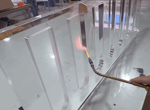
Tool Condition and Geometry
I’ve seen a dull cutter turn a great setup into a surface nightmare.
Sharp tools leave cleaner cuts and more consistent finishes. Tool geometry, especially rake angle, nose radius, and clearance, also affects the surface texture left behind.
If the tool is wrong with the material or job, roughness will show up fast.
Machine Rigidity and Vibration
A solid and well-tuned machine makes a world of difference. Even slight vibration or flex during cutting can leave chatter marks and rough patterns.
If your workholding setup isn’t tight or the spindle is unstable, the finish suffers.
Sometimes improving surface roughness is as simple as tightening bolts and checking your fixture.
Cutting Parameters
Feed rate and cutting speed are two of the easiest things to tweak and two of the most overlooked. A slower feed can result in a finer surface, while too fast will leave behind tool marks and ripples.
Cutting speed also impacts chip flow and surface quality, especially when working with difficult materials.
Getting this balance right often takes some trial and error.
Coolant and Lubrication
I used to think coolant was mostly about temperature control, but it plays a huge role in surface finish too. A good cutting fluid reduces friction and helps flush chips away from the cutting zone.
That means less heat, fewer tool marks, and a cleaner surface overall.
Poor lubrication, on the other hand, leads to built-up edges and erratic finish quality.

6. Applications and Industry Examples
Surface roughness plays a different role depending on where and how a part is used. Here are some real-world examples across industries where getting the surface finish right is critical:
- Aerospace: Aircraft engine parts, like turbine blades and housings, require extremely smooth finishes to reduce drag and resist fatigue. Even a slight deviation in surface texture can shorten part life or affect fuel efficiency.
- Automotive: Pistons, crankshafts, and valve seats must balance smooth movement with proper oil retention. Too much roughness can cause leaks or premature wear, while too little can lead to poor lubrication.
- Medical Devices: Surgical implants and instruments rely on specific finishes to ensure hygiene and biocompatibility. A rough surface may harbor bacteria, while an overly polished one may interfere with how bone or tissue interacts.
- Hydraulics and Pneumatics: Sealing surfaces like cylinder bores or valve seats need precise roughness to ensure tight, leak-free performance. If the surface is too rough, seals can tear or fail; if too smooth, they might not grip properly.
- Injection Molding: The surface of the mold affects both part release and the cosmetic finish of the molded product. High-gloss parts require polished molds, while textured finishes are often achieved with EDM or bead blasting.
- Tool and Die Making: The performance of stamping dies and cutting tools depends on controlled surface finishes to maintain sharpness and reduce wear. Poor surface control can lead to burrs, inconsistent cuts, or tool breakage.
- Consumer Electronics: Housings and contact points in devices like smartphones need controlled textures for aesthetics and usability. Surface roughness affects not just how products look, but how they feel and wear over time.
- Food and Beverage Processing: Piping, tanks, and nozzles must have finishes that reduce contamination and are easy to clean. Surface roughness here is a safety and regulatory issue, not just a quality concern.

7. Tips for Specifying Surface Roughness in Design
I’ve made the mistake of over-specifying surface roughness on a drawing just to play it safe. The result? Unhappy machinists, higher costs, and a lot of back-and-forth that could’ve been avoided.
If you want to keep production smooth and budgets in check, surface finish has to be specified with intention.
Only Call Out What Actually Matters
Not every surface needs a finish spec. Focus on areas that affect sealing, movement, or mating with other parts. If it’s cosmetic or non-functional, let the manufacturer choose what’s most efficient. Over-specifying just adds unnecessary time and cost without any benefit.
Know What the Process Can Achieve
Every manufacturing method has a natural surface finish range. CNC turning, grinding, casting, and polishing all produce different textures. Before assigning a Ra value, talk to your supplier or machinist to see what’s realistic. Pushing for an ultra-smooth surface that the process can’t easily deliver will just lead to problems.
Make Sure the Drawing Is Clear
I’ve seen drawings with multiple finish symbols and no explanation of where they apply. That confusion can delay production or lead to incorrect finishes. Use clean notes like “Ra 3.2 on all machined faces” or apply symbols clearly next to the relevant surfaces. The easier it is to interpret, the better the results will be.
Match Roughness With Function
A sealing surface might need Ra 0.8, but a structural support could be fine with Ra 6.3. Ask yourself how each surface will interact with the rest of the assembly. If it needs to hold a gasket, move smoothly, or resist wear, then roughness becomes critical. When in doubt, think performance first and polish second.
Conclusion
You made it through Ra, Rz, symbols, standards, and strategies. That means you’re serious about doing things better.
Surface roughness is functional. When you understand it, you prevent problems and save time.
Which spec on your drawing deserves a second look?
You’re ready. You’ve got the knowledge. Now make it count.
Contact MachMaster today to get expert help on precision surface finishes for your next project.