
You’ve got an idea in your head. Maybe it’s a bracket, a cover, or a full part.
But now you’re stuck.
How do you turn an idea into a real prototype, without wasting time or cash?
I’ve been there too.
When I started, I thought I had it figured out. I sent my CAD files to a shop. Waited for the quote. But I didn’t know the right material. I didn’t check the bend radius. I didn’t even think about how thick the metal should be.
It came back wrong. Twice. And I had to start over. That mistake cost me money. And weeks of delay.
That’s why I’m writing this. Because once you know how sheet metal prototyping really works, you’ll stop guessing. You’ll move faster. And you’ll spend smarter.
In this guide, you’ll learn:
- What a sheet metal prototype is
- How the process works, step-by-step
- What affects the price
- The common mistakes people make
Whether you’re building your first part, improving a product, or buying parts for your team—you’re in the right place.
So, let’s dive in!
1. What is a Sheet Metal Prototype
I still remember holding my first prototype: clean folds, sharp corners—but it didn’t fit. We forgot to account for the bend radius. That mistake cost us a week and a hard conversation with the client.
That’s when I realized: a prototype isn’t just a draft. It’s your safety net.
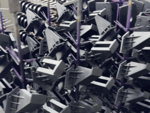
A sheet metal prototype is a real, testable version of your part. It’s made using actual materials like aluminum or stainless steel and built with the same processes—cutting, bending, punching—as production parts.
Why build one?
To check:
- Fit and tolerance
- Structural strength
- Material behavior and finish
- Integration with other parts
- Manufacturability
It’s how you catch errors early and reduce waste.
You’ll use prototypes during:
- Product development
- Supplier trials
- Pilot production
- Client or investor demos
If precision or performance matters, don’t skip this step. A prototype is where your CAD model becomes real—and where mistakes get fixed before they cost you more.

2. Key Benefits of Sheet Metal Prototyping
If you’re serious about speed, precision, and staying ahead of delays, then prototyping with sheet metal isn’t a “nice-to-have”—it’s a non-negotiable.
I’ve seen what happens when teams skip this step. Missed tolerances. Fit issues. Blowups on the production floor. But I’ve also seen how much smoother—and faster—things go when prototyping is baked into the process from day one.
Here’s what you gain when you do it right:
Rapid Iteration with Real Materials
Nothing tests your design like real metal.
When you build your prototype using the same or similar materials to your final product—aluminum, stainless steel, galvanized, you’re seeing true performance, not simulation. That means strength, weight, flexibility, and thermal behavior show up exactly as they would in production.
You can iterate faster because you’re cutting, forming, and assembling using the actual processes:
- Laser cutting
- Bending and forming
- Spot welding or riveting
Change a bend angle today, test tomorrow. No tooling delays. No weeks lost waiting for updates. That kind of speed saves money and momentum.
Cost-Effective Testing
Hard tooling costs can crush your budget early on. A single misstep in a production run? It’s not just expensive, it’s embarrassing.
Sheet metal prototyping lets you test without upfront tooling investment. You’re working with soft tooling setups and digital workflows, which means:
- You spend less up front
- You catch design-for-manufacturing issues early
- You prevent late-stage fire drills
I’ve seen teams avoid tens of thousands in rework costs by flagging an interference problem, just because they prototyped first.
Scalable to Mass Production
Prototyping with real processes sets you up for a clean production handoff.
You’re not just testing “if it works.” You’re confirming that the part can be repeated accurately, efficiently, and with minimal changes. The same laser paths, the same bend radii, the same material handling.
Once it’s dialed in, scaling becomes a matter of volume, not reengineering. That’s how you hit your launch dates without firefighting.
3. Design Considerations for Sheet Metal Prototypes
Here’s something I learned the hard way: even the best prototype shop can’t save a bad design.
If you skip the fundamentals, you’ll waste time, money, and trust. Tight tolerances, wrong bend radii, poor material choices—they all come back to bite you in prototyping. That’s why the smartest teams front-load their projects with clear, practical design-for-manufacturing thinking.
These are the essentials you need to get right before your first cut.
Apply Realistic Tolerances
Sheet metal isn’t injection molding. It’s dynamic. It bends, stretches, and rebounds.
If you apply overly tight tolerances—like ±0.005” across a bent surface, you’re setting yourself (and your shop) up for frustration. You may hit those numbers once, but not reliably. And in production, repeatability is everything.
Tip: Keep your tolerances as loose as functionally possible, especially across bends and long spans. Save the tight fits for mating parts that truly demand it.
Respect the Bend Radius
Every material has a minimum bend radius. Go too tight, and you risk cracking or deforming the part.
Here’s what that means in real life: your beautiful CAD design may look perfect, but on the brake press, it’ll fold like a bad poker hand if you don’t spec the right radii.
A general rule?
- Use 1x material thickness as your internal bend radius for steel
- For aluminum, go 1.5x or more to reduce cracking risks
Your prototyping partner should be able to advise you here. They should actively review drawings and flag radius issues before they go into production. That kind of feedback loop is priceless.
Choose Fastening Methods Early
How you connect your sheet metal matters—especially if you’re building enclosures, chassis, or frames. Depending on strength, cost, and assembly method, you’ll want to decide early between:
- Spot welding
- Self-clinching fasteners (PEM nuts)
- Screws or rivets
- Tabs and slots for tool-less assembly
Watch Out for Overcomplication
It’s tempting to overdesign. Extra bends. Extra flanges. Fancy perforations.
But every added feature means added complexity, longer lead times, and higher costs. Worse, some designs may require custom tooling, defeating the whole point of fast prototyping.
Stick with flat patterns that form cleanly. Combine parts only when necessary. And lean on experienced partners like MachMaster, who can offer DFM guidance before you hit “send” on that RFQ.

4. Steps of Sheet Metal Prototyping Process
A successful sheet metal prototype isn’t built by accident. It follows a proven process, each step connected, each one critical.
Whether you’re handling the design in-house or coordinating with a trusted shop, this roadmap keeps your timeline and budget on track.
Step#1 Concept and 3D CAD Modeling
Every prototype starts as a concept, but it doesn’t become real until it’s in CAD.
You or your design team will translate the concept into a 3D model, usually using platforms like SolidWorks, Fusion 360, or AutoCAD. This is where you define:
- Part dimensions and geometry
- Bend locations and radii
- Hole placements, slots, and cutouts
- Assembly features (tabs, fasteners, etc.)
Design for Manufacturability (DFM) should be applied at this stage. That means thinking ahead about how the part will actually be made, not just how it looks on screen.
Step#2 Material Selection
Choosing the right metal is more than a spec box. It’s a decision that affects:
- Strength and rigidity
- Weight and thickness
- Corrosion resistance
- Surface finish
- Cost
Common prototype materials include:
- Aluminum 5052/6061: Lightweight, easy to form, corrosion-resistant
- Cold-rolled steel: Strong, low-cost, ideal for painted or coated parts
- Stainless steel 304: Durable, clean finish, often used for enclosures
A good supplier will walk you through options and recommend the best fit based on your design and application.

Step#3 Flat Pattern Creation and CAM Preparation
Once the 3D model is finalized, it’s unfolded into a 2D flat pattern.
This pattern is fed into CAM (Computer-Aided Manufacturing) software to generate the cut paths, bend lines, and tool instructions. This is also when machine tolerances, kerf compensation, and bend allowances are applied.
Pro tip: If you’re working with a partner, they’ll handle this translation and double-check your files for manufacturability before fabrication begins.

Step#4 Cutting, Bending, and Forming
Now it’s time to shape metal.
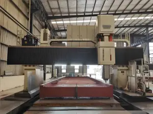
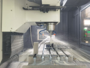
- Laser Cutting or CNC Punching: The flat sheet is cut to size with high precision
- Bending: Brake press machines fold the metal along programmed lines
- Forming & Rolling: For parts needing curves or channels
- Deburring: Edges are cleaned up for safety and assembly
At this point, your design is no longer just digital, it’s physically taking shape.

Step#5 Joining and Assembly
If your prototype involves multiple parts, it’s time to bring them together. This may include:
- Spot welding or MIG/TIG welding
- Fastener insertion (PEM nuts, rivets, screws)
- Tack welding for temporary placement
Even in prototyping, proper joining matters. You want the prototype to behave like the final product, fit, strength, and assembly-wise.

Step#6 Surface Finishing
A prototype doesn’t always need finishing—but when it does, it should match the final look and feel as closely as possible. Popular finishes include:
- Powder coating
- Anodizing (for aluminum)
- Plating (zinc, nickel)
- Bead blasting or brushing
Surface finish can impact more than looks, it affects corrosion resistance, wear performance, and even tolerances.

Step#7 Testing, Feedback, and Revisions
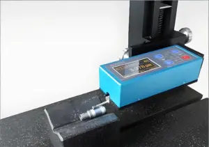
Now comes the critical part: evaluation. You (or your engineering team) will review the prototype for:
- Fit and assembly accuracy
- Structural integrity under load
- Alignment with surrounding parts or systems
- Aesthetic approval (if relevant)
Expect to iterate. Most successful teams go through 1–3 prototype rounds before locking final specs. And with a responsive prototyping partner, those rounds can move fast.

5. Sheet Metal Prototype vs. Other Prototyping Methods
Not all prototypes are created equal. Each method has its strengths and its limits.
Early in my career, I worked with a team that started prototyping an industrial housing with 3D printing. The model looked slick. But the moment we tested it under real mounting torque, it cracked. Turns out, plastic and powder sintering don’t replicate cold-rolled steel very well.
We lost 2 weeks, and it cost the client’s confidence. That was the last time we chose prototyping for convenience instead of function.
Here’s how sheet metal prototyping stacks up against other options:
| Prototyping Method | Best Used For | Material Used | Turnaround Time | Production Readiness | Limitations |
| Sheet Metal Prototype | Functional prototypes of enclosures, brackets, structural parts | Aluminum, steel, stainless, galvanized | 2–7 days (average) | High — same tools/methods used in production | Less ideal for organic shapes or complex 3D geometries |
| 3D Printing (FDM/SLA/SLS) | Concept models, ergonomic testing, light-duty assemblies | PLA, ABS, resin, nylon | 1–3 days | Low — very different from final metal part | Lacks strength, poor thermal performance, doesn’t reflect real-world metal use |
| CNC Machining | High-precision mechanical parts, low-volume production | Metals, plastics, composites | 5–10 days | Medium — production-grade tolerances | Expensive for sheet-like forms; slow for large flat parts |
| Injection Molding | Plastic parts for mass production validation | ABS, PP, PC, other polymers | 2–6 weeks (due to tooling) | High — same as production | High tooling cost; not suitable for low volumes or early-stage prototyping |
| Vacuum Casting | Small batches of plastic parts with production-like finishes | Polyurethane resins | 1–2 weeks | Low — limited durability | Not scalable; parts are cosmetic and degrade faster |
| Foam or Cardboard Models | Early-stage ideation or packaging concepts | Foam board, cardboard | Hours to 1 day | None — purely conceptual | Not functional; no material relevance; just for shape exploration |
When function matters, and it always does, in production-focused environments, sheet metal prototypes give you the best signal:
- You test real behavior under mechanical stress
- You see true tolerances and bend dynamics
- You build a direct bridge for production without surprises
I once had a client try 3D printing their enclosure first. Looked great on the desk, but melted during their product’s heat testing cycle. We went to sheet metal, and the prototype passed everything on the first try. That version is still in production today.
6. Common Mistakes to Avoid in Sheet Metal Processing
There’s nothing worse than watching a production run stall because of something you could’ve caught during prototyping.
I’ve seen it happen firsthand: a client insisted on skipping DFM review to save a day. The parts came back warped from bad bend geometry, and the shop floor lost an entire week reworking the batch. That one shortcut costs more than the entire prototype budget.
That’s why I tell every client, every time: the cost of a mistake always outweighs the cost of doing it right the first time.
Here are the most common pitfalls I’ve seen, so you don’t repeat them:
Rushing Without a Finalized Design
Speed is great—until it turns into chaos.
Many teams jump to fabrication before the design is locked. Every revision after cutting means new files, new tooling paths, and more labor. That adds up quickly.
Lock your design before cutting. You’ll save time, money, and frustration on both ends.
Ignoring Design for Manufacturability (DFM)
You can draw anything in CAD. But can it actually be made?
Overly tight tolerances, unrealistic bend angles, or complex geometry without proper reliefs—these are red flags that shops should spot immediately. But if you ignore DFM and push it through anyway, expect delays, part failures, or total redesigns.
Bring your fabricator early. Let them review. Listen.
Choosing the Wrong Material for the Job
All metals are not created equal.
Using 6061 aluminum when you need deep forming? Expect cracks. Choosing stainless when mild steel? You’re just burning the budget.
Always match material to performance needs and finish requirements. And when in doubt, ask your supplier. Some manufacturers often recommend alternative materials based on project goals that end up saving both time and money.
Overcomplicating the Design
Fancy features look good on a render. But every flange, notch, or custom cut increases lead time and cost. Overengineering is one of the fastest ways to derail a prototype and frustrate your fabricator.
Rule of thumb: If it doesn’t add clear functional value, leave it out. Your prototype should be as simple as it can be, while still testing what it needs to.
Skipping a Fit Check or Test Assembly
This one hurts.
I’ve seen prototypes come back flawless on paper, perfect cuts, exact bends, but the team forgot to test how it fits into the actual product. Cue the scramble.
Don’t just inspect parts. Assemble them. Fit them. Use them. A 5-minute dry fit can save you 5 days of delays.

7. Tips for Choosing the Right Sheet Metal Prototyping Partner
You can have the cleanest design files, the right materials, and a tight timeline, but if your prototyping partner can’t deliver, it all falls apart.
This is where many teams stumble. They focus on price and lead time, but overlook communication, capability, and experience. I’ve worked with vendors who ghosted mid-project. I’ve worked with others who caught design flaws I missed. And the difference wasn’t the quote, it was the partnership.
Here’s how to pick the right one, before it costs you:
#1 Look for Industry-Specific Experience
Every product category has its own challenges. Enclosures for electronics, brackets for industrial machinery, housings for fitness equipment—each comes with different standards for strength, tolerances, or finishes.
Your partner should understand your industry, not just “do metal.” Ask to see samples, case studies, or specific experience related to your product type.
#2 Evaluate Communication and Responsiveness
Fast quoting is great. Fast clarification is better. You want a team that:
- Asks the right questions
- Flags issues early
- Offers alternative solutions when needed
- Provides updates without you chasing them
The smoothest prototyping experiences I’ve had came from teams who communicated before I even knew there was a problem.
#3 Verify In-House Capabilities
Outsourcing is common, but too much of it introduces risk. Look for a shop with in-house control over:
- Laser cutting or CNC punching
- Bending/forming
- Welding and fastener insertion
- Finishing (even if subcontracted, they should manage it directly)
This reduces handoffs, delays, and blame-shifting if something goes wrong.
#4 Ask About Their DFM Process
The right shop won’t just build your prototype—they’ll improve your design.
Partners like Machmaster are known for their proactive DFM feedback. They’ll review your files, point out bend issues, suggest better materials, and help you avoid expensive mistakes. That kind of support doesn’t show up in the quote, but it saves you on the back end.
Conclusion
You’re no longer stuck. You’ve got the tools now.
We talked about the process, the pricing, and the pitfalls. You’ve seen how a small mistake—like wrong thickness or tight bends—can slow everything down.
But now you’re ready.
Start with what you know. Build from there.
Make your idea real.
That part you’ve been holding in your head? It’s closer than you think.
Want help turning it into metal? Contact us today!
Dive Deeper Into Our Resources
Looking for more diverse service options? Browse through our handpicked selections:
- Anodizing Service
- Cnc Milling Service
- Cnc Turning Service
- Injection Molding Service
- Cnc Machining Service
For some insightful reads, we’ve curated a list of recommended articles just for you:
Still haven’t found what you’re looking for? Don’t hesitate to contact us. We’re available around the clock to assist you.