
You can spend hours getting your cut files perfect but one wrong bend, and your part becomes scrap.
I’ve been there more than once.
In one job, I made the mistake of ignoring grain direction. I focused so much on cutting layout and kerf that I didn’t think ahead to the bends. The shop followed my drawing, bent the parts, and sent them back with cracks running straight through the corners.
It was my fault and it was expensive.
If you’ve ever had something like that happen, this guide is for you. Inside, I’ll show you how these two processes work together. You’ll learn how to plan for accuracy, reduce mistakes, and finally get consistent results.
Let’s start!
1. Understanding the Basics
Before you dive into cutting and bending, it helps to step back and look at the bigger picture. That way, everything makes more sense later on.
I remember watching a new team member struggle with a simple project. The part looked easy on paper. But he didn’t realize cutting and bending weren’t just steps—they were two very different processes. Once he understood that, things clicked. He started asking better questions, and we got fewer errors.
Let’s start with what sheet metal fabrication actually is.
What Is Sheet Metal Fabrication?
Sheet metal fabrication is how flat sheets of metal are turned into usable parts. You start with a blank sheet. Then you cut it, bend it, and sometimes weld or join it.
It’s used in nearly every industry. From car panels to kitchen equipment, HVAC ducts to lighting brackets—fabricated metal is everywhere.
Common materials include:
- Aluminum: Lightweight, corrosion-resistant, and easy to form
- Steel: Strong and cost-effective, but heavier
- Stainless steel: Doesn’t rust and looks clean, often used in food or medical equipment
- Copper: Good for electrical parts or decorative items
- Brass: Often used in plumbing or decorative finishes
Each material reacts differently to cutting and bending. That’s why you need to match your tools and methods to what you’re working with.
Now let’s break down the two core steps: cutting and bending.
Cutting vs. Bending
It’s easy to mix them up if you’re new to fabrication. But each step plays a separate role in the process.
- Cutting is the act of slicing the metal sheet into smaller shapes or outlines. You might use a laser, waterjet, or snips depending on the job.
- Bending is what happens after cutting. It’s how you fold the flat part into a 3D shape. You use tools like press brakes and dies to do this.
Cutting usually comes first. It sets the size and shape. Bending comes next, shaping the part to match the drawing.
Think of it like baking cookies. Cutting is using the cookie cutter. Bending is folding them into the right shape, if you need a 3D cookie, that is.
Have you ever tried to bend a part that was cut wrong? It doesn’t work. That’s why both steps need to be accurate and planned together.
Knowing the basics gives you a solid starting point. Once you understand what each process does and where it fits, you can make smarter decisions about materials, methods, and even suppliers.
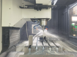
2. Sheet Metal Cutting
Sheet metal cutting is the process of slicing flat metal sheets into smaller parts or shapes. It’s often the first step before bending or forming. How well this step is done affects everything that comes after. If your cuts are off, bends won’t line up, holes won’t match, and parts may not even fit together.
I’ve learned the hard way: bad cuts can throw off an entire project. Whether you’re working with a supplier or doing things in-house, knowing the options—and what affects accuracy—can save you time, money, and stress.
Let’s start with some basic cutting methods.
Manual Cutting Tools
Manual tools are often used for simple cuts or quick jobs. They don’t need power or programming, but they do have limits.
- Shears or snips: These are like heavy-duty scissors for metal. Good for thin sheets or small trim jobs. But the edges can turn rough or wavy if you’re not careful.
- Guillotine cutters: These use a straight blade to chop through metal, kind of like a giant paper cutter. They work better for straight lines and longer cuts. Still, accuracy depends on how steady your setup is.
Where things can go wrong
With manual tools, the human factor matters. A shaky hand, a worn blade, or uneven pressure can all lead to crooked lines, uneven edges, or extra scrap.
Ready to step up from hand tools? Let’s move on to machines that do the cutting for you.
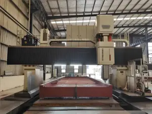
Mechanical and CNC Cutting Methods
These methods use machines to cut with more speed and precision. Some are manually controlled, while others follow a digital file.
| Method | Precision | Material Thickness | Heat Effect | Edge Quality | Cost Level |
| Laser Cutting | High | Thin to medium | Yes (can warp) | Very clean | Moderate to high |
| Plasma Cutting | Medium | Medium to thick | Yes (more heat) | Rougher edges | Lower |
| Waterjet Cutting | Very high | Thin to very thick | No | Very clean | Higher |
| CNC Punching | Medium | Thin to medium | No | Good (with right tools) | Moderate |
So how do you choose? That depends on your material, design, and how sharp the final part needs to be.
Before picking a method, it helps to know what affects cutting quality in the first place.
Key Factors That Affect Cutting Accuracy
Here are a few things that can throw off your cuts:
- Material type and thickness: Harder metals or thicker sheets need stronger tools and slower feed rates. Too much pressure can cause edge defects.
- Tool wear: Dull blades, clogged nozzles, or worn punches can lead to ragged edges or missed dimensions.
- Machine calibration: If your machine isn’t aligned or zeroed in, your cuts will shift over time.
- Heat distortion: Laser and plasma cutters generate heat. On thin sheets, that can make edges curl or warp.
Even the best machine won’t help if these issues aren’t controlled. So how do you stay accurate?
How to Improve Cutting Precision
Here’s what works in real shops:
- Use digital designs: Start with a DXF file (Drawing Exchange Format). These files give machines exact shapes and sizes to follow. No guessing.
- Match your machine to the job: Use waterjet for thick or delicate materials. Laser is great for thin sheets with fine detail. Plasma works fast on thicker steel.
- Keep equipment in shape: Clean your nozzles. Sharpen your blades. Check your calibration. It sounds basic, but skipping these steps is a common cause of bad cuts.
- Add lead-ins and lead-outs: These are short lines added to the start and end of each cut in your design. They let the tool start cutting before it hits the actual part edge. That helps prevent burn marks or overcuts.
Ever had a part come back wrong even though the design looked perfect? It might not be the drawing, it might be the setup. Ask your vendor if they’re using lead-ins, or if they regularly check calibration.
Cutting and bending are closely connected. A mistake in one can throw off the other. That’s why getting the cutting step right is so important.
Is your current setup giving you clean, consistent parts? Or are you spending time fixing cuts that don’t line up?
Next, we’ll look at the bending process. It has its own challenges but when paired with clean cuts, the results speak for themselves.

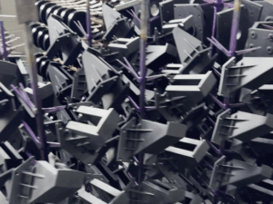
3. Sheet Metal Bending
After cutting comes the next step: bending. If the cut is clean but the bend is off, the part still won’t work. That’s why bending needs just as much attention.
I once had a supplier send me parts that looked fine until we tried to assemble them. Turns out, the bends were just a few degrees off. That small mistake caused delays and rework. Since then, I’ve paid close attention to how bending is done, and who’s doing it.
Let’s start with the most common techniques.
Common Bending Techniques
There’s more than one way to bend sheet metal. The right choice depends on your part shape, material, and production volume.
- Press brake bending: This is the most common method. A machine called a press brake pushes the metal into a V-shaped die to form an angle.
- Roll bending: This method uses rollers to create large curves or cylinders. It’s slower but useful for parts like tubes or curved panels.
Now let’s look closer at three common styles used with press brakes:
- V-bending: The metal is pressed into a V-die. It’s flexible and works for many angles.
- Air bending: The punch pushes the sheet into the die, but doesn’t touch the bottom. It allows for more angles but can be less accurate.
- Bottoming: The punch presses the metal all the way to the bottom of the die. This gives more consistent angles, but it needs the right die size.
Once you’ve chosen a method, the next step is planning the bend itself.
Understanding Bend Allowance and Bend Radius
To bend metal without cracking or misalignment, you need to plan for the bend. That’s where bend allowance and bend radius come in.
- Bend allowance is the extra material needed to make a bend. When metal bends, it stretches. If you don’t leave room for that stretch, your part ends up short.
- Bend radius is the inside curve of the bend. If it’s too tight, the metal may crack. If it’s too wide, the bend won’t hold its shape.
To plan this, many designers use the K-factor. This is a number that helps calculate how much the metal stretches during bending. You don’t need to be an engineer to use it. Most CAD software includes it automatically.
Getting this right is key. A small miscalculation here can throw off your whole part.
Now let’s look at the tools that make these bends happen.
Tools Used in Sheet Metal Bending
The main tool is the press brake. It uses force to push the metal into shape.
But the real detail comes from the dies and punches. These are the parts that touch the metal and form the bend.
There are different tooling types, such as:
- V-dies for standard bends
- Radius dies for softer curves
- Gooseneck punches for tight spots
The shape and size of the tooling directly affect bend accuracy. If the wrong tool is used, the angle or radius could be wrong even if the machine is perfect.
Even with the right setup, some mistakes still happen. Here’s what to watch out for.
Mistakes That Affect Bend Accuracy
Bend issues often come from simple things:
- Grain direction: Metal has a “grain,” like wood. If you bend against the grain, the metal can crack or spring back more.
- Wrong die size: If the die is too narrow or wide, the bend won’t match your drawing.
- Incorrect bend allowance: Misjudging how much stretch the metal needs leads to short or long parts.
- Springback: After bending, some metals try to return to their original shape. If you don’t account for this, your part will be under-bent. To fix this, you can over-bend slightly or use bottoming to hold the angle.
Have you ever measured a part and wondered, “Why is this bend off by 2 degrees?” It might be springback—or a tool mismatch. Either way, small things lead to big problems if left unchecked.
Accurate bending is part math, part setup, and part experience. If cutting is the start, bending is the make-or-break point for part fit and function.

4. Design Tips for Accurate Cutting and Bending
Even with the best machines, a bad design can ruin your part. That’s why getting the drawing right matters just as much as the tools you use.
Optimize Your CAD Files
Start with clean, accurate CAD files. These are digital drawings used to control cutting and bending machines. If your file has missing dimensions, odd line breaks, or overlapping features, it can lead to bad cuts.
One time, we got a file where the bend lines weren’t clear. The part looked fine on screen—but the press brake operator had to guess. That guess cost us two full sheets of material.
Stick to standard bend radii. These are common, proven bend sizes that most shops already have tools for. Using standard sizes makes your part easier to bend and cheaper to produce.
Design for Manufacturability (DFM)
Design for Manufacturability means making parts that are easy to produce. Sounds simple, but many designs fail here.
A few tips to keep in mind:
- Keep bends away from holes and edges. Close spacing can cause tearing or distortion.
- Avoid stacking tight tolerances. If every step needs perfection, one small shift ruins the whole part.
- Think about how the metal behaves. Some materials spring back after bending. Others crack if bent too sharply.
Have you ever had a part that looked perfect on paper but didn’t work in real life? That’s often a DFM issue.
5. Tolerances and Quality Control
Even if your cuts and bends look right, small errors can still cause big problems. That’s why tolerances and quality checks matter.
I once approved a batch of parts that seemed perfect at first glance. But when we tried to assemble them? Nothing lined up. The issue wasn’t the bend angle—it was a small shift in hole position. That mistake could’ve been caught early with better quality control.
Let’s start by understanding tolerances.
Standard Tolerance Ranges in Sheet Metal Work
Tolerances are the allowed differences between the drawing and the actual part. No machine is perfect, so a small range of variation is expected.
Common standards include:
- ISO 2768: Used widely in international projects
- ANSI Y14.5: Common in North America
In most cases, cutting tolerances range from ±0.1 mm to ±0.5 mm. For bending, angle tolerances might be ±1°. Prototypes may need looser tolerances. Production parts, especially those that need to fit into assemblies, often need tighter ones.
Now that you know what to expect, let’s talk about how to measure it.
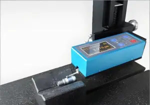
How to Measure Accuracy
To check part accuracy, you’ll need the right tools:
- Calipers: Good for measuring outside and inside dimensions
- Micrometers: Offer high precision for tight spaces
- Angle finders: Used to check bend angles
For inspections, you can use:
- Visual checks: For burrs, warping, or wrong cuts
- Dimensional checks: Using hand tools or gauges
- CMM (Coordinate Measuring Machine): A high-precision tool for complex parts
After measurement, what happens next?
Common Quality Control Practices
Shops use a few methods to catch issues early:
- First article inspection: Checking the first piece off the machine
- Batch sampling: Measuring a few parts from each batch to spot trends
- Fit checks: Testing how parts go together in an assembly
Tolerances may look like small numbers, but they can make or break a project. Taking the time to measure and check your parts will save you trouble later on.

6. Working With a Sheet Metal Manufacturer
Choosing the right sheet metal partner can make your job easier or a lot harder. Before you start production, it helps to ask the right questions and share the right details.
What to Ask Before You Start
Not every manufacturer works the same way. Some focus on high-volume production. Others are better suited for prototypes or short runs. Asking good questions upfront saves time and avoids surprises.
Here are a few things to ask:
- What machines do you use? The type of equipment affects precision, lead time, and what materials they can handle.
- What tolerances can you consistently hit? It’s better to know their typical performance than to assume.
- Can you help with Design for Manufacturability (DFM)? Some shops will review your drawings and give feedback to make the part easier and cheaper to produce.
If a shop can’t answer these clearly, it may be a red flag.
Once you’ve chosen a manufacturer, how you communicate with them makes a big difference.
And if you’re looking for a reliable partner who can handle everything from small trials to full-scale production, MachMaster is worth a look. With tight tolerance capabilities and experience across 500+ global projects, they know how to keep things precise and moving.
Communication Tips for Accurate Results
Even skilled shops can’t read minds. If your files are vague or missing details, they might guess—and that can lead to mistakes.
To improve accuracy, always:
- Provide clear CAD files and 2D drawings: DXF or STEP files work well, paired with dimensioned PDFs
- Specify material type and thickness: “Stainless steel” isn’t enough—give the grade and gauge
- Highlight critical tolerances: Let them know which dimensions matter most and where accuracy really counts
The right sheet metal manufacturer is more than a vendor, they’re part of your team. Ask good questions, send complete files, and make your priorities clear. The better the communication, the better the results.
Conclusion
Cutting and bending sheet metal may sound simple. But getting it right takes planning, clear designs, and a partner who knows what they’re doing.
You’ve learned what matters:
- How cuts and bends work together
- What tools give you cleaner results
- Why tolerances and inspections protect your bottom line
I’ve been where you are waiting on late parts, fixing warped bends, guessing why nothing fits. You don’t have to stay there.
Start now. Tighten up your drawings. Ask better questions. Partner smarter.
What part of your process needs work? Ready to take it further?
Contact us today to talk through your next project.
More Guides and Tips to Explore
We’ve got more for you! These articles provide more tips and guidance to keep you on track:
Still haven’t found what you’re looking for? Don’t hesitate to contact us. We’re available around the clock to assist you.