
Shaft parts are used in machinery, automation equipment, drive systems, and mechanical assemblies. Although many shafts have a simple cylindrical shape, their designs often include steps, grooves, keyways, splines, threads, and other features that require different machining operations.
The machining method depends on the shaft geometry, material, dimensional requirements, and how the part connects with other components.
This guide explains the common features found on machined shafts, the processes used to produce them, and the design considerations that affect manufacturing.
1. Common Shaft Features and Their Machining Requirements
A shaft’s shape is usually determined by its function. Different features provide support, positioning, fastening, or torque transmission.
Straight and Stepped Shafts
A straight shaft has a relatively consistent outside diameter along its length. A stepped shaft has several diameter sections designed for bearings, gears, pulleys, seals, or other components.
CNC turning is commonly used to produce these round features. The diameter, shoulder position, and length of each section should follow the drawing requirements.
Shoulders and Grooves
Shoulders provide locating surfaces or stops for assembled components. Grooves may be used for retaining rings, seals, or other mechanical features.
These features are commonly produced during turning. Groove width, depth, and position need to match the mating component or assembly requirements.
Keyways and Flats
Keyways allow a shaft to connect with gears, pulleys, and couplings through a key. Flats provide a surface for positioning, clamping, or fastening.
CNC milling is commonly used to produce these non-round features. The width, depth, and position of a keyway are important for proper fit and torque transmission.
Splines
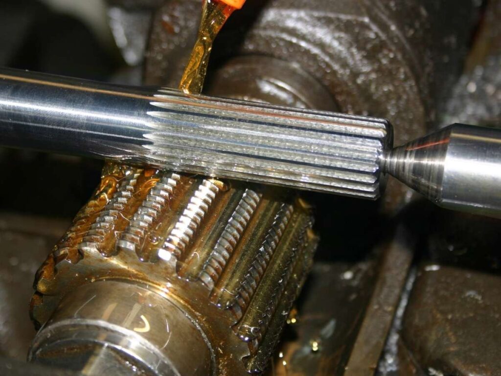
Splines are formed by a series of teeth along the shaft surface. They are used to transfer torque between connected components while maintaining the required engagement.
Spline machining methods depend on the spline profile, dimensions, accuracy, and production quantity. Milling, broaching, and other suitable processes may be considered.
Threads and Cross Holes
External or internal threads allow shafts to connect with fasteners, retainers, and other components. Cross holes may be used for pins, lubrication, or fastening.
Thread turning, tapping, thread milling, and drilling are common methods, depending on the feature design and material.
Bearing Seats
Bearing seats are shaft sections where bearings are installed. Their diameter, fit, surface finish, and relationship to other shaft features affect assembly and operation.
CNC turning is commonly used to produce bearing seats. Precision grinding may be considered when tighter dimensional control or a smoother surface is required.
2. Common Machining Processes for Shaft Parts
Most machined shafts require one or more machining operations. The process route depends on the geometry and the required accuracy.
CNC Turning
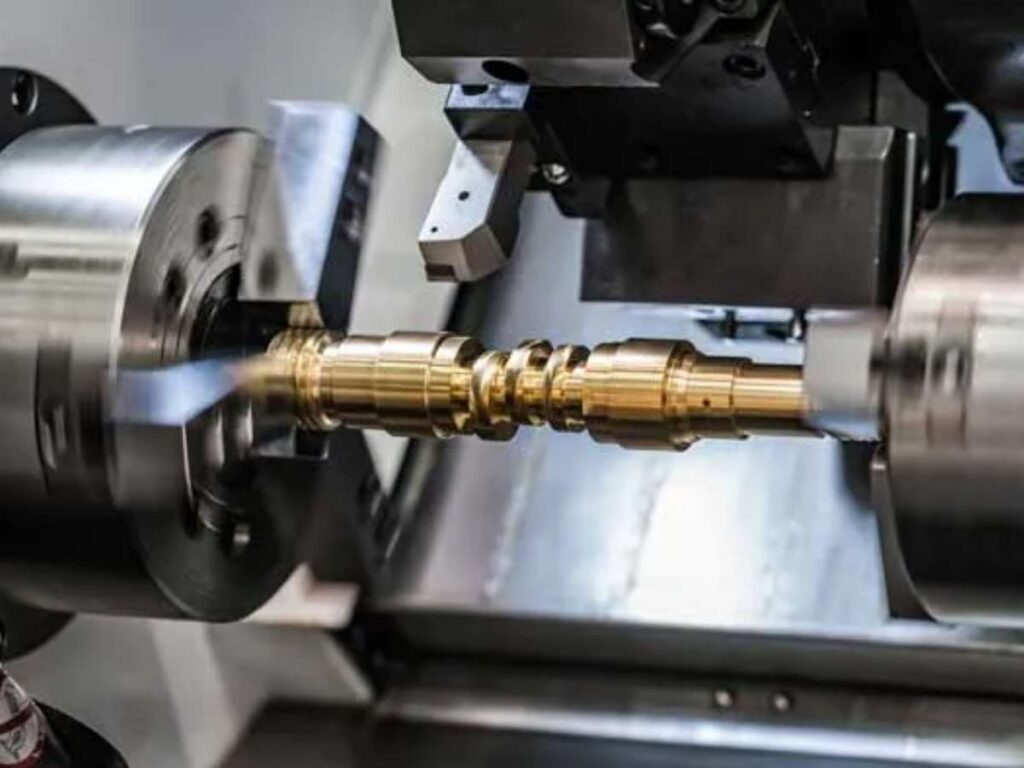
CNC turning is one of the main processes used for shaft parts. The workpiece rotates while a cutting tool removes material to create round features.
Typical turning operations include:
- Outside diameter machining
- Stepped diameter machining
- Shoulder and groove cutting
- Taper turning
- External and internal threading
- Facing and boring
Turning is particularly suitable for shafts with cylindrical profiles and multiple diameter sections.
CNC Milling
CNC milling is used when a shaft includes features that cannot be produced by turning alone.
Common examples include:
- Keyways and keyseats
- Flats and slots
- Cross holes and mounting features
- Non-round profiles
- Certain spline designs
For parts with both turned and milled features, the machining plan needs to account for the relationship between the cylindrical surfaces and the additional features.
Drilling and Threading
Drilling produces holes in shaft components, including axial holes and cross holes. Boring may be used to enlarge or improve an existing hole.
Threads can be produced through tapping, thread turning, or thread milling. The method depends on the thread location, size, material, and required accuracy.
Spline Machining
Spline machining produces the teeth that allow a shaft to engage with a mating component.
The appropriate process depends on whether the design uses an involute spline, straight-sided spline, or another profile. The spline specification and mating requirements should be provided with the drawing.
Precision Grinding
Grinding may be used after turning or heat treatment when a shaft requires tighter dimensional control or a smoother working surface.
It is commonly considered for bearing seats, hardened shaft sections, and other precision contact surfaces.
3. How Different Shaft Features Affect Machining
The features on a shaft determine the machining operations, setups, tooling, and inspection requirements.
| Shaft Feature | Common Machining Method | Important Considerations |
|---|---|---|
| Outside diameters | CNC Turning | Diameter and length |
| Shoulders | CNC Turning | Position and squareness |
| Grooves | CNC Turning | Width, depth, and location |
| Keyways | CNC Milling or Broaching | Width, depth, and alignment |
| Flats and slots | CNC Milling | Position and dimensions |
| Axial holes | Drilling and Boring | Hole diameter, depth, and position |
| Threads | Thread Turning, Tapping, or Thread Milling | Thread size and specification |
| Splines | Milling, Broaching, or other suitable methods | Profile and mating fit |
| Bearing seats | Turning and, where required, Grinding | Diameter, fit, and surface finish |
A shaft with only round features may be produced mainly through turning. A design with keyways, flats, cross holes, or splines usually requires additional operations.
For complex shafts, the machining sequence should also consider how each feature will be located and measured. This helps maintain the relationship between critical surfaces.
4. Additional Processes for Shaft Parts
Some shaft components require additional processing after the main machining operations.
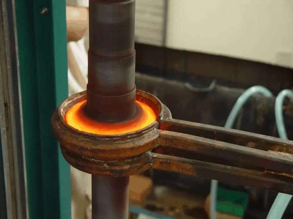
Heat Treatment
Heat treatment may be specified to achieve certain hardness, strength, or wear properties. The required method depends on the material grade and the intended working conditions.
Because heat treatment can affect dimensions and straightness, the machining sequence should account for any finishing operations that may be required afterward.
Surface Finishing
Surface finishing may be required for corrosion resistance, wear performance, appearance, or other functional requirements.
Common options depend on the shaft material and application. The drawing should specify the required finish or performance requirement rather than simply stating that a shaft needs a finished surface.
Deburring and Final Inspection
Machining can leave sharp edges and burrs around grooves, holes, threads, and milled features. These need to be addressed before the parts are assembled or shipped.
Final inspection should focus on the dimensions and functional features identified in the drawing.
5. What to Consider When Designing Machined Shaft Parts
A good shaft design should meet its mechanical requirements while remaining practical to manufacture.
Define the Critical Dimensions
Identify the dimensions that control assembly and function, such as bearing seats, mating diameters, shoulder positions, and keyway dimensions.
Not every dimension needs the same tolerance. Applying tighter tolerances only where necessary can help control manufacturing costs.
Consider the Machining Access
Deep grooves, narrow slots, internal features, and complex profiles may require special tooling or additional setups.
Reviewing these features before production can help identify manufacturing difficulties early.
Specify Keyways and Splines Clearly
For keyways, provide the required width, depth, length, and position. For splines, include the applicable profile and dimensional specifications.
If the shaft must fit an existing gear, coupling, or other component, providing the mating-part information can help clarify the requirements.
Consider Bearing and Mating Fits
Bearing seats and other mating diameters should be specified according to the required fit.
The drawing should identify the relevant tolerance and, where necessary, the fit relationship between connected components.
Include Surface Requirements Where Needed
Surface roughness is important on certain contact areas, bearing seats, and sealing surfaces. Specify the required finish on the relevant drawing features instead of applying the same surface requirement to the entire shaft.
6. CNC Shaft Machining at Machmaster
Machmaster provides CNC machining for custom metal and plastic components, including shaft parts with turned diameters, shoulders, grooves, holes, threads, and milled features.
Based in Xiamen, China, Machmaster has 20 years of manufacturing experience and 40+ CNC machining machines.
Our manufacturing capabilities include:
- CNC turning for cylindrical shaft features
- CNC milling for keyways, flats, slots, and other machined details
- Prototype, low-volume, and batch production
- ISO 9001-certified quality management
- In-house inspection using VMM and conventional measuring equipment
Our team can review your drawings, material requirements, critical dimensions, and production quantity before quotation.
For more information about our machining capabilities, visit our CNC Turning Services and CNC Milling Services pages.
Get a Quote for Machined Shaft Parts
Have a shaft drawing or sample ready?
Send Machmaster your 2D drawing or 3D CAD file. Include the material, quantity, critical dimensions, keyway or spline requirements, and any specified surface finish or heat treatment.
Our engineering and sales teams can review your requirements and respond within 24 hours.